Vertical or Horizontal Blinds Automation Project
Important Disclosure
Although I have successfully printed this design over and over with 100% success rate using the 3DFillies White PLA+ on my Prusa i3 MK3 printer and the stock PEI spring steel print bed, that doesn’t mean that this will work the same on your printer.
I am providing you all the design files, code and know-how in good faith and I will not be liable for any damages that may be caused directly or indirectly while making, or using this device.
By downloading any files and using any of the information posted on this site you agree to the above.
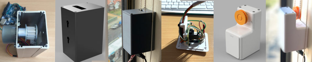
Now for the fun stuff … this project started with a need to close my blinds on a west facing window in the afternoon, while I was away. Especially in summer, the sun in Australia can do devastating things to the objects that it shines onto directly. Plus, it drastically increased the temperature in the room. As with any design project, it goes through various stages of prototyping. Bellow is a snapshot of my design process. The early working prototype had a light sensor built in to control the blinds based on the intensity of sunlight falling on the window. That turned out to be impractical and unnecessary.
I already have a home automation setup that integrates Apple’s HomeKit and Homebridge for DIY and other device integrations. However, for this device I designed an API that can be used by other home automation solutions.
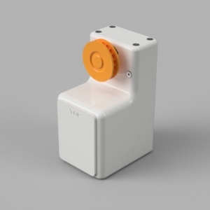
I will start describing the project with what the final device looks like.
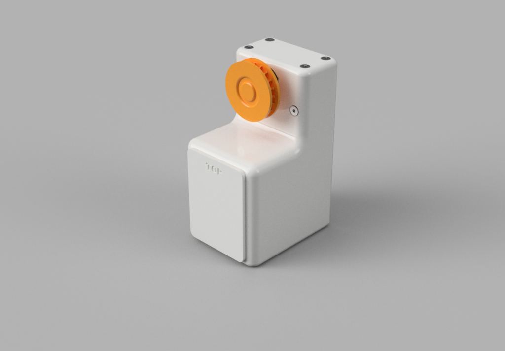
The Finished Product
The dimensions are approximately 64mm deep, 47mm wide and 92mm tall. The cog wheel was designed to pull a ball chain with 5mm diameter balls. The device connects to your home WiFi and the web based configuration allows you to customise the start and stop or open and close position of your blinds. The device attaches to the wall by double sided tape.
Short video of the making of …

Components and Skill set
You will require the following components and skills to build this project:
Skills
- Arduino IDE and basic knowledge uploading code to a compatible board
- Basic soldering skills
- 3D Printing and slicing an STL file
- General assembly skills
Components
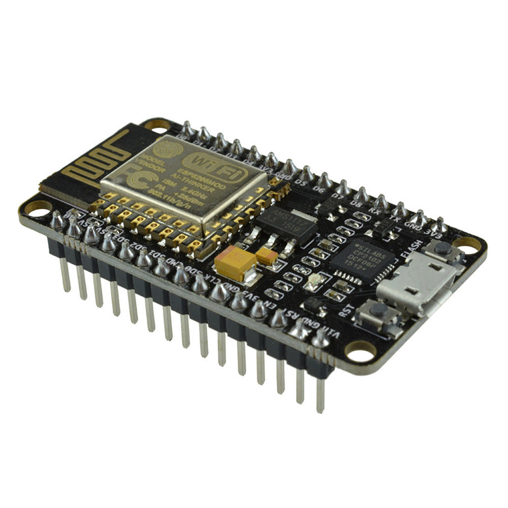
- 1x Node MCU CP2102 ESP8266 (I suggest get two just in case)
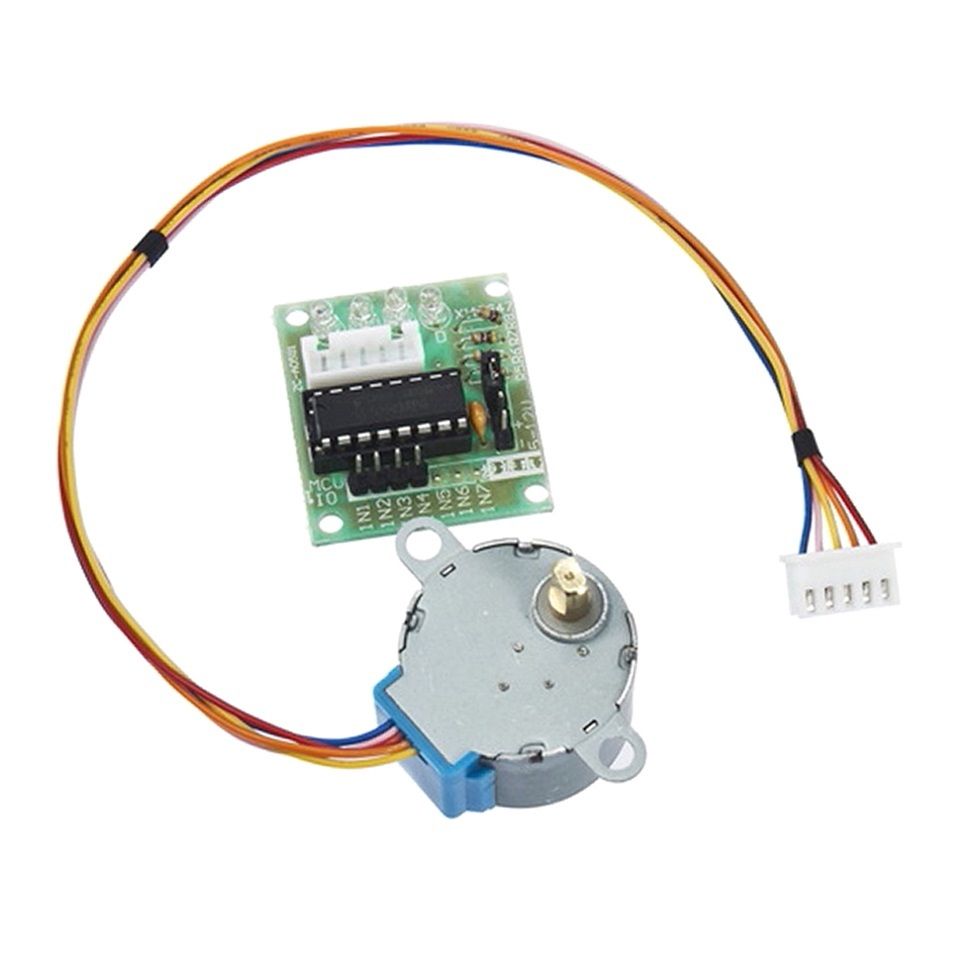
- 1x Stepper motor 28BYJ-48 5v with ULN2003 driver
- 18x M2.5 x8mm Countersunk screw and 2x nuts
- 2x M4 x5mm Steel Hex Head Cup Point Grub screw
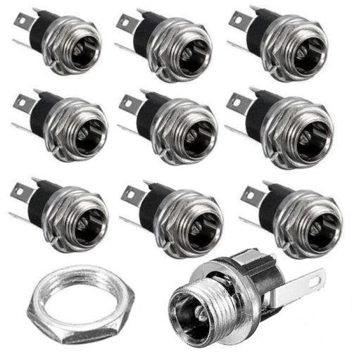
- 1x 5.5mm x 2.1mm DC power plug
- 1x 5v Power Supply with a 2.1mm DC plug
- STL Files for the body, cog wheel, top and bottom covers and the wall mount. These are attached to this post.
- Arduino Sketch for the Node MDU, also attached to this post.
NOTE: The linked Amazon products are example only. You can use similar products as long as they match the specification listed. The respective images for the above components are displayed below.
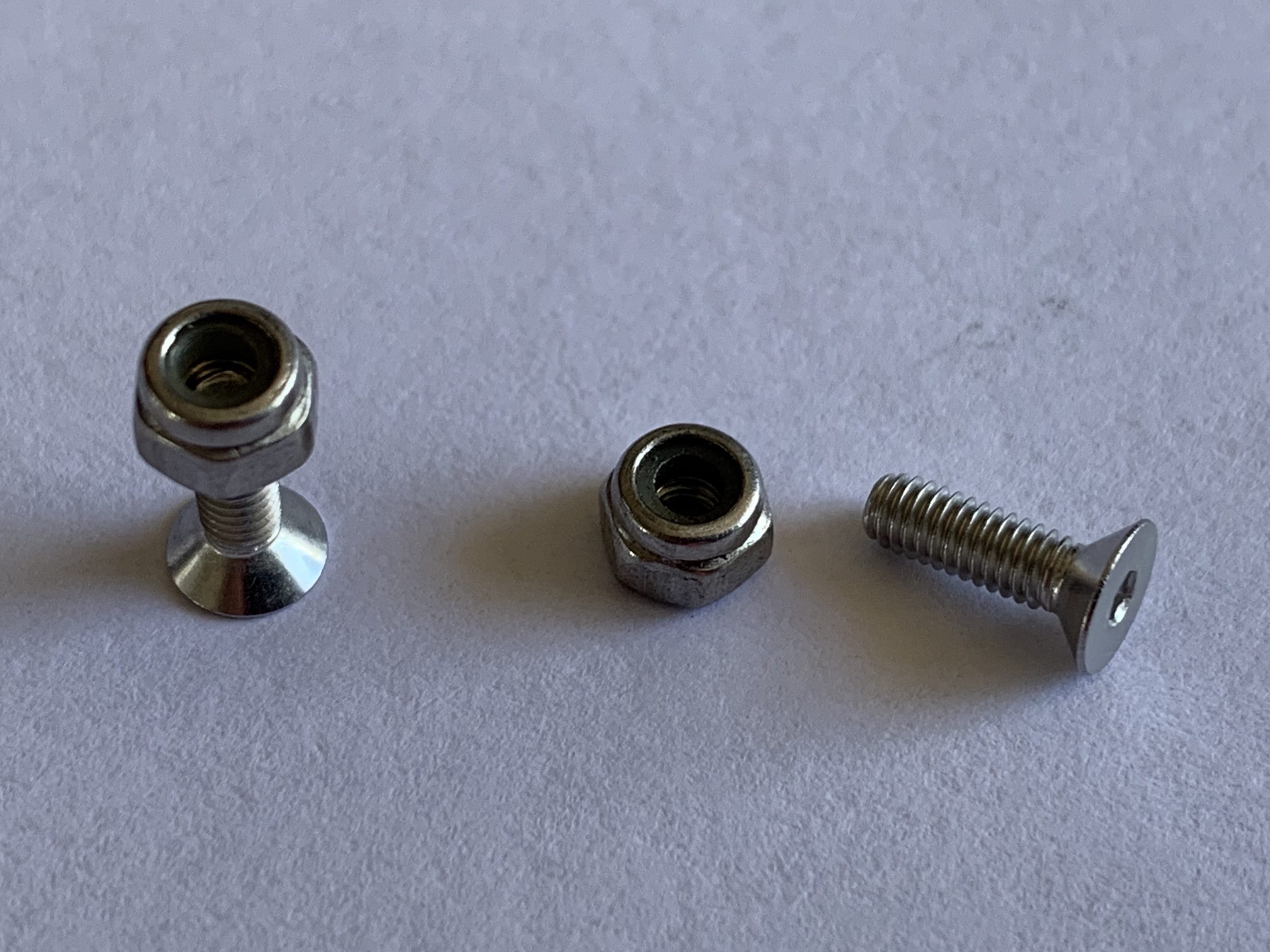
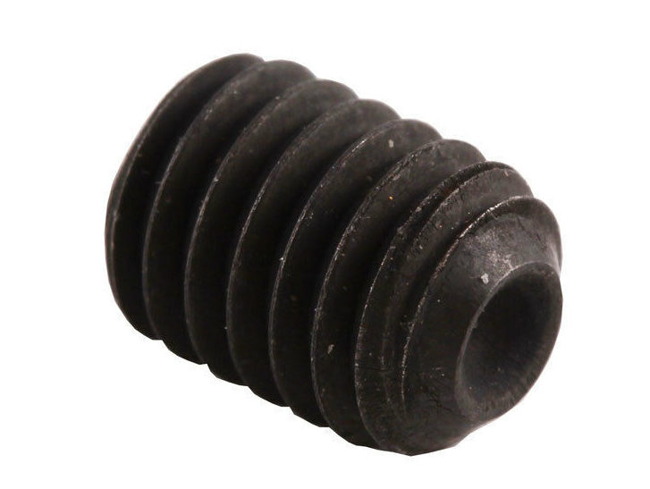
The screws I used were all 8mm long. The screw holes in the body of the device should go right through so if the screw is a little longer than it should not matter.
I used countersunk heads for all the external mounts and button or any cap screw to mount the NodeMCU and the Motor driver. I also experimented with self threading mini screws – they also work well for all the mounting points that screw into the plastic. The motor mount will however require a nut on the other end to hold it in place.
3D Printing
The Base
I have designed the base such that it can be printed, upright and without supports but that probably requires some level of 3D printing experience. All the internal overhangs have a 45deg support so most 3D printers should be able to handle this without supports. The L shaped part will be bridged by the printer, again post printers should be able to handle bridging this small gap. If you want to get the hanger holes perfect, you could add supports there.
The Top and Bottom Lids
The top and bottom lids should be printed on their flat surfaces and without supports.
The Cog
The cog is the only component that I would print with supports. That is because of the dimples on the inside. Also you should print it on its largest flat surface.
Assembly
Here is the schematic of the connections. The ULN2003 I listed in the above parts list will only have 4 connection points to the NodeMCU and two for power and ground. Ignore the 3 red connection point in the diagrams lower left. One thing I noticed, the order of the pins of the ULN2003 board to NodeNCU sometimes differs from board to board. Hook it up the way you see it then reverse the connection if it is not working for you i.e D1 -> 1st (top most), D5 -> 2nd etc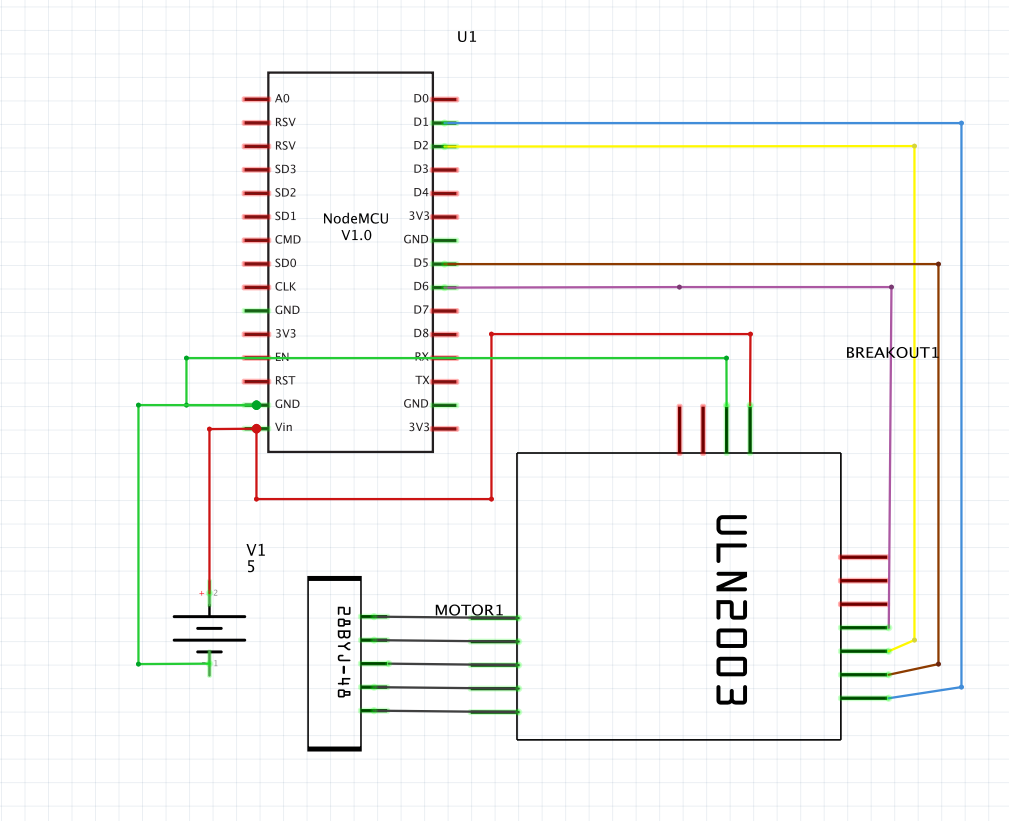
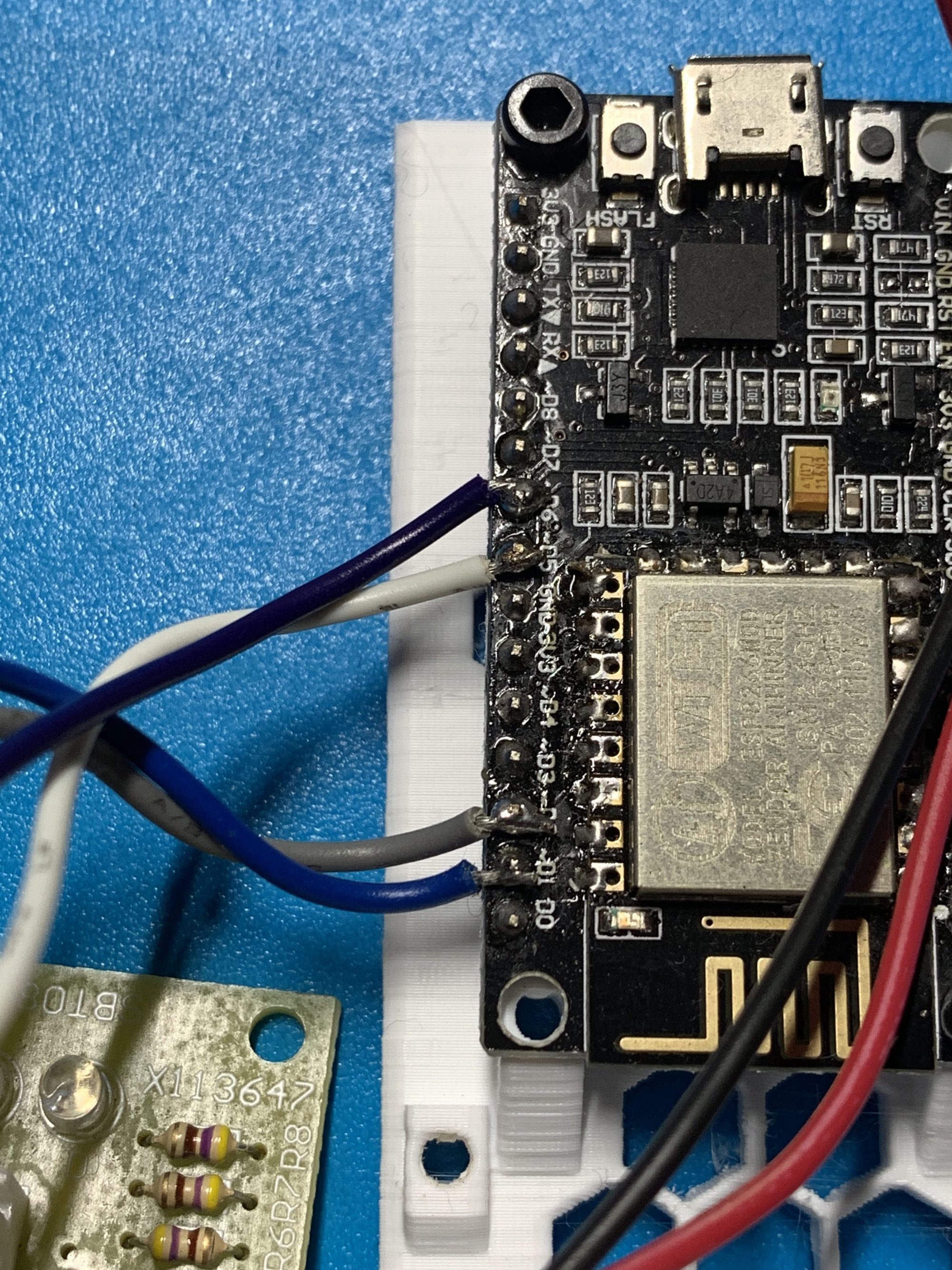
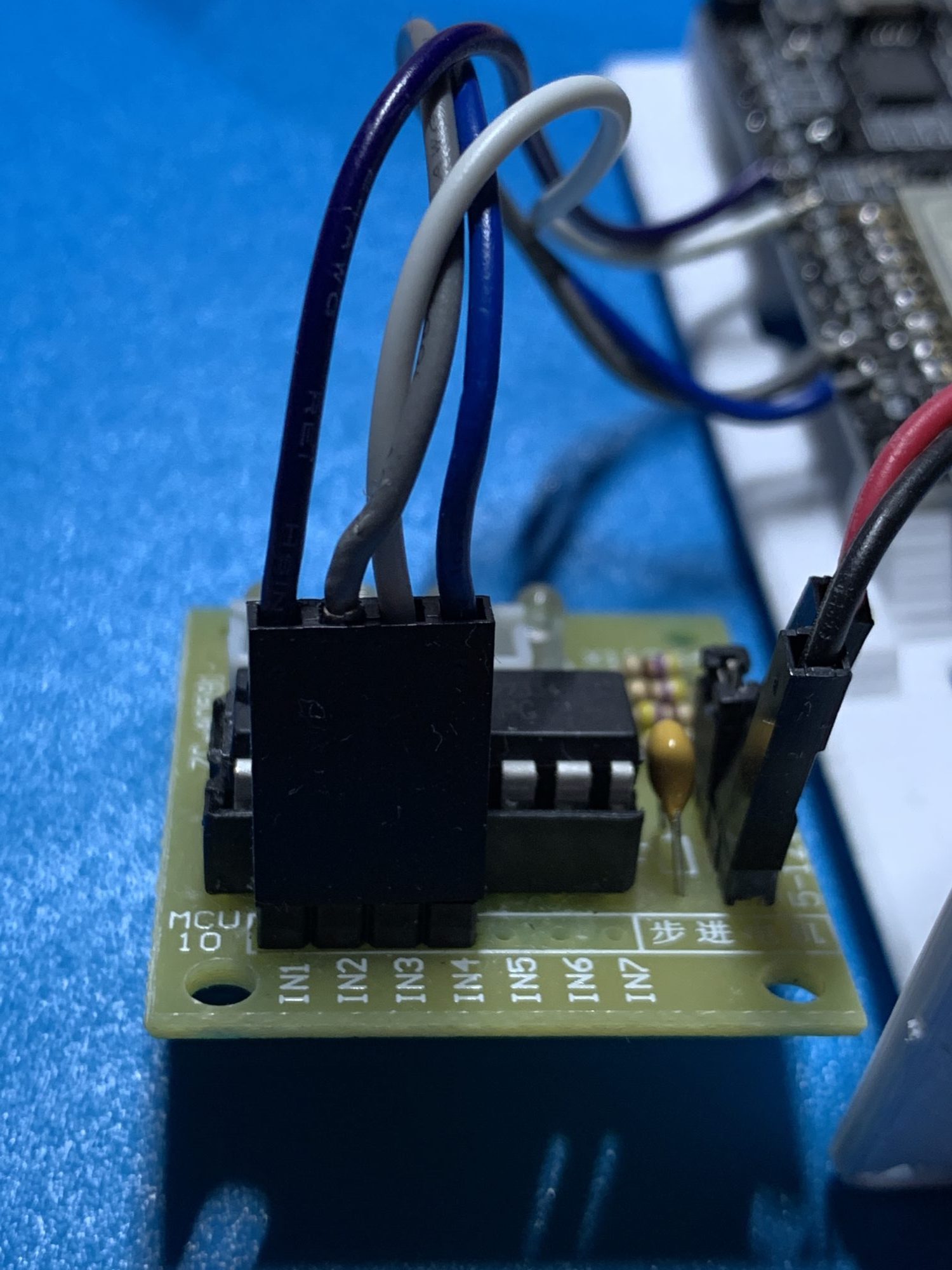
Here are a few images of how to solder the wires between the motor controller and the MCU. These may give more clarity than the schematic above. The thickness of the wires used is approx. 24AWG.
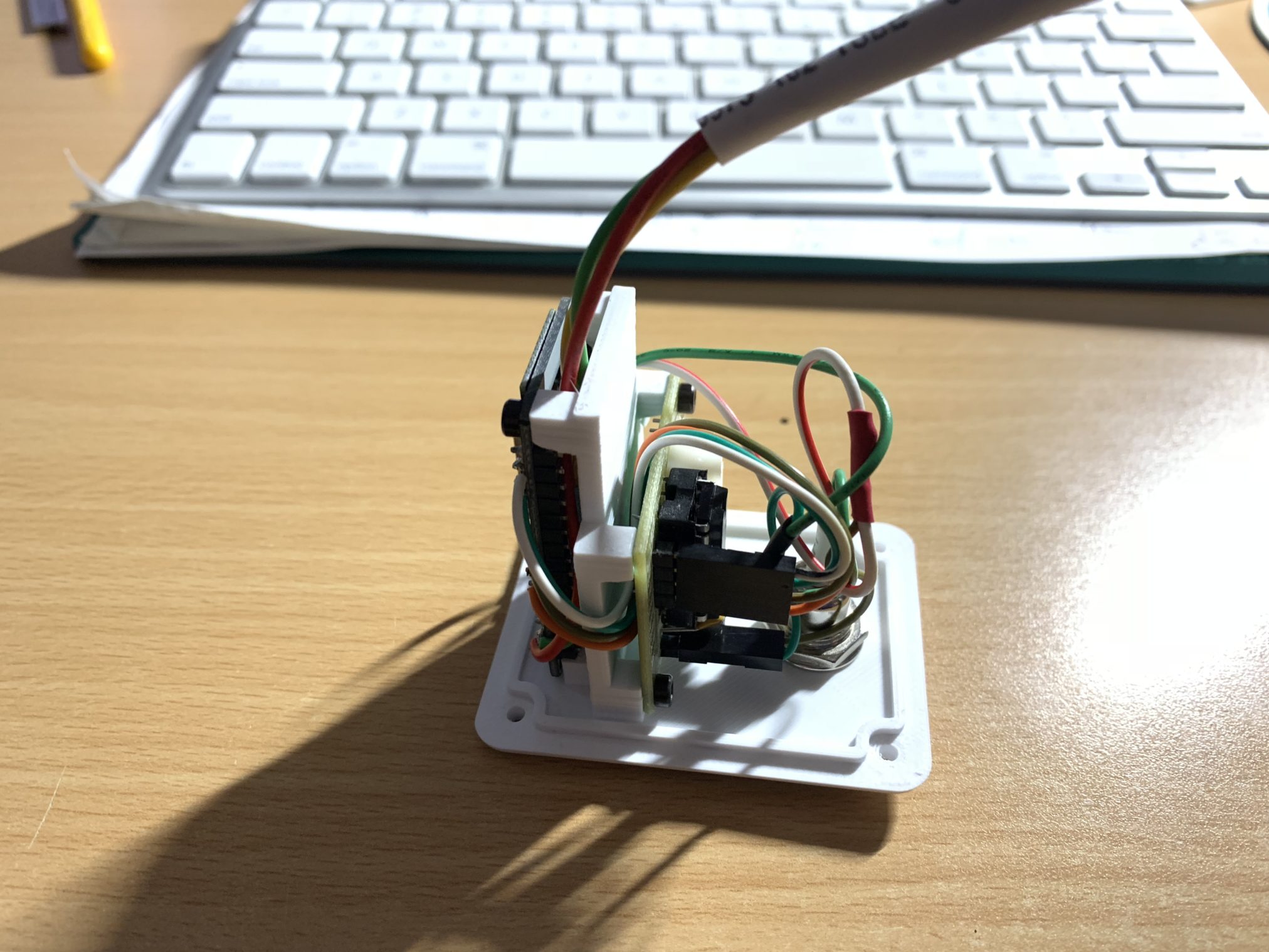
Here is an image of the assembly of the the electronics. The stepper motor driver fits on the inside of the vertical mount wall near the DC plug. The nodeMCU fits on the other side. Keep your wires short as there is not much room once you put the body on. Also ignore the bundle of wires sticking out at the top – that’s from a version which included a light sensor – I gave that up as it was impractical. The mounting location of my AutoBlinds device was always in the shade and no access to sunlight.
Software and API
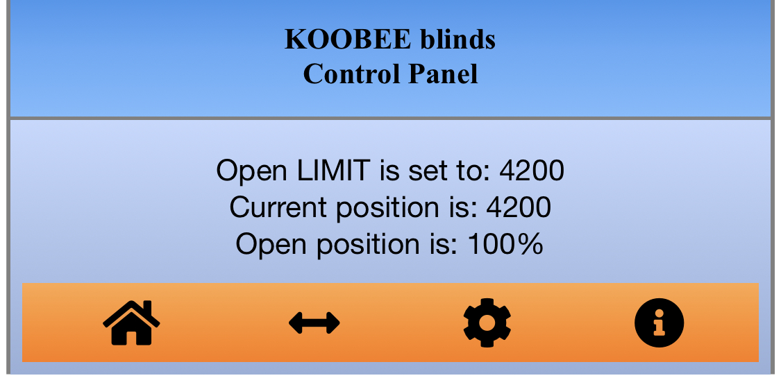
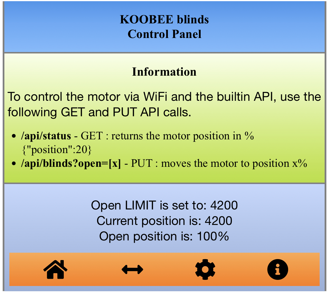
Once the device is connected to your WiFi network, you can access the web interface through http://your-device-ip/ to get to the home page that displays the current status of your device.
http://your-device-ip/api/help – will display the help information and the api options.
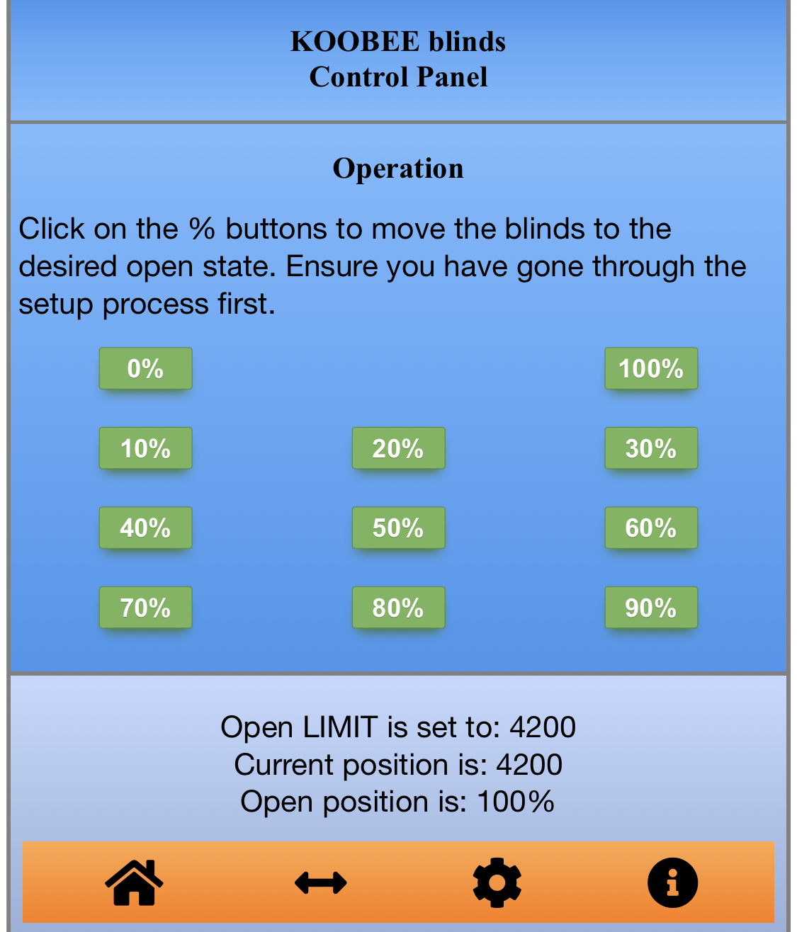
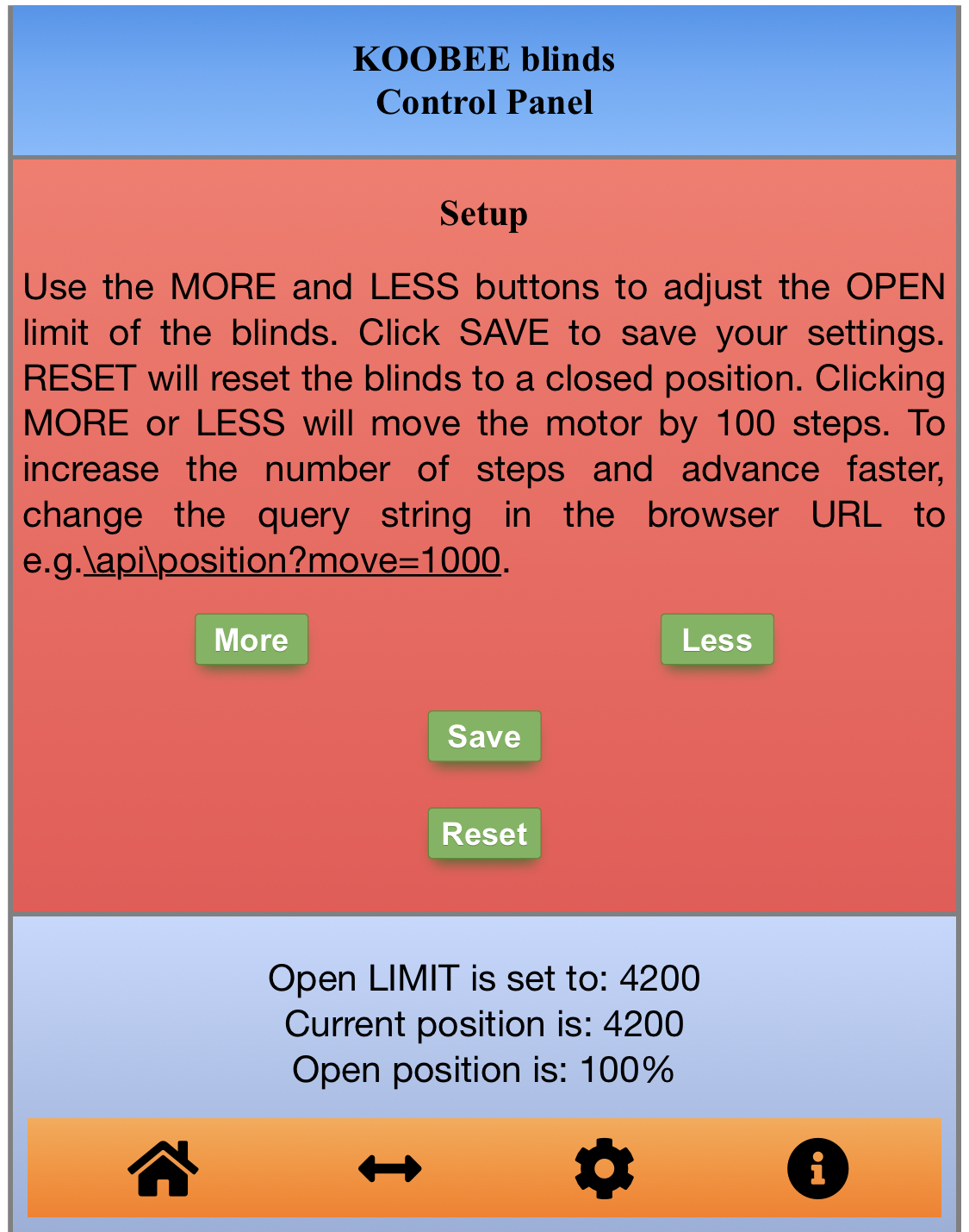
You can use the icons on the bottom of the home page to navigate the web interface. From the web interface you can setup that END position of your blinds.
To configure your device, close your blinds manually, wrap the chain around the cog and mount the device on the wall with light tension o the chain. Then from the web interface, select the GEAR icon and open the blinds electronically until you reach the desired state. Then click SAVE. Thats it. now you can open, close or partially open or close your blinds buy seating the following api command:
http://your-device-id/api/blinds?open=20 {to open the blinds 20%}
Bellow are some example screen shots from the wed GUI
WP 3D Thingviewer Lite need Javascript to work.
Please activate and reload the page.
Files Download
The Code
Here is the list of all currently available code for the project. The main part is the Arduino Sketch. You will need this to program the NodeMCU.
If you would like to try to integrate the DIY Smart Blinds withe either Apple Homekit (Homebridge required) or Amazon Alexa through the Samsung Smart Things, I am providing my experimental code. Use at your own risk.
| Description | Link |
| Arduino Sketch | GitHub link |
| Homebridge plugin / Homekit | GitHub link |
| Samsung Smart Things – device handler | GitHub link |
Some additional info also posted on Thingiverse
NOTE: This post is a work in progress and additional content details and material is still being added.