Automation project for vertical and horizontal blinds
Following on the popularity of the DIY SmartBlinds v1 device found here, I attempted to update the design and make it a bit slimmer, easier to print and easier to assemble. This design uses all the same electronic components as v1 except for the power connector. In this version, I upgraded the power connector to micro usb and yes you can power this device from almost any USB power adapter. I have also updated the software to operate when mounted on the left or the right hand side of the window. So here it is:
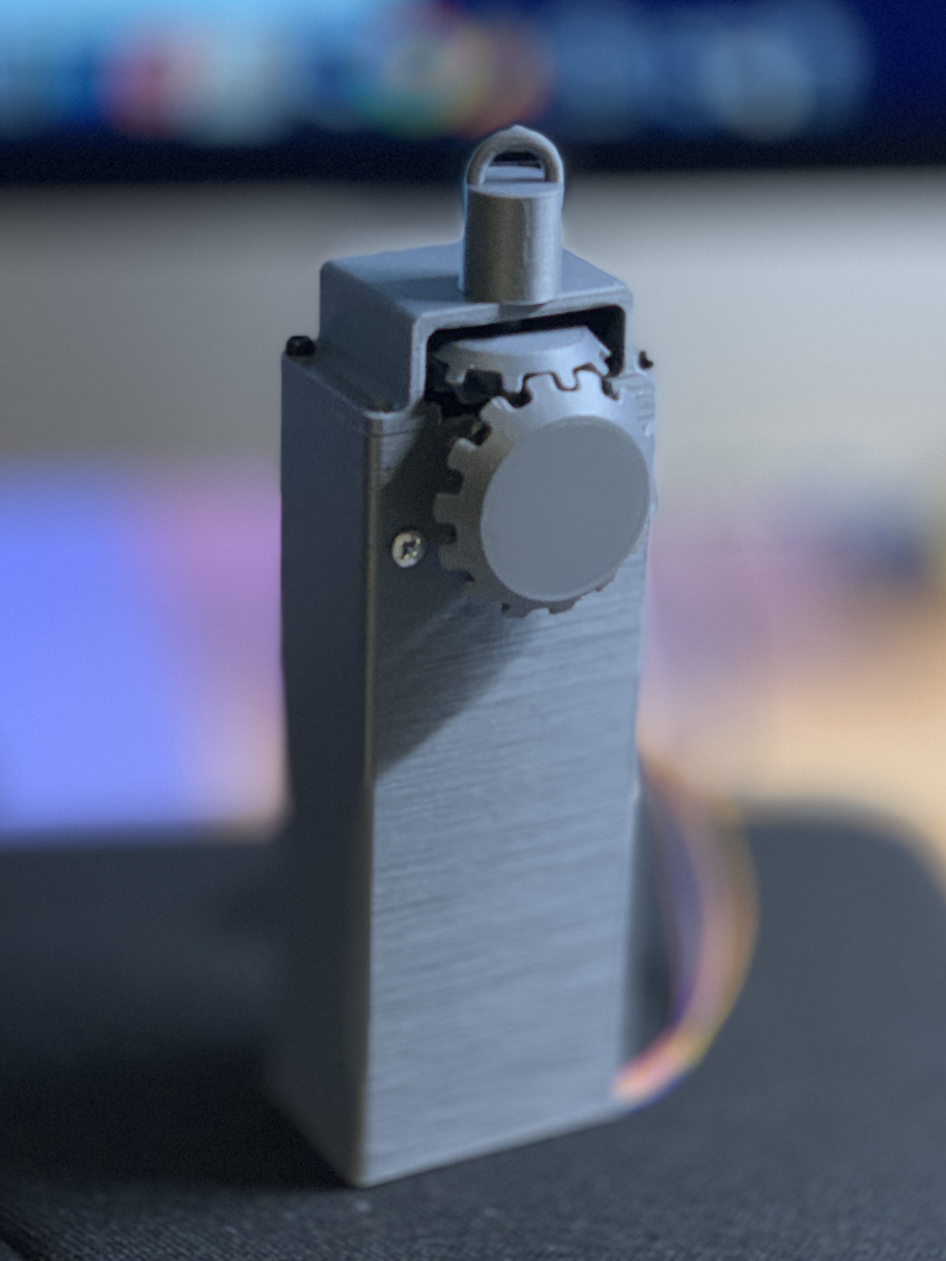
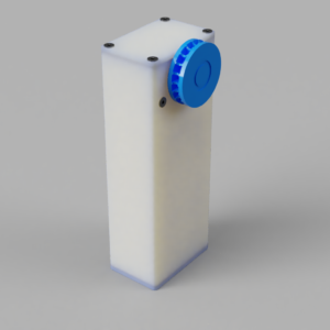
The dimensions of this design are as follows. The body height is 125mm, width 47mm and depth 31mm. The distance from the wall to the face of the cog wheel is about 40mm, if you use the included wall mount then you should add another 3 mm.
This design has been extensively tested in my own home environment. The SmartBlinds device is mounted on the inside of the window frame in semi-direct sunlight. It has run on standby for over 226 days and has actual use over 450 hrs without the need for maintenance. Although I had very positive results yours may be different hence this is not a guarntee.
3D Printing
The printable components are made up of Top Lid, Bottom Lid with MCU mount, the Body and an optional Wall Mount. The assembly of the printed components is straight forward.
All components have been designed to be printed without supports. For printing I used my Prusa I3 MK3 printer. I use 0.2 layer height with 15% infill and PLA+. Even after months of usage in the Australian heat and semi-direct indoor sunlight, my prototype devices still work and operate perfectly.
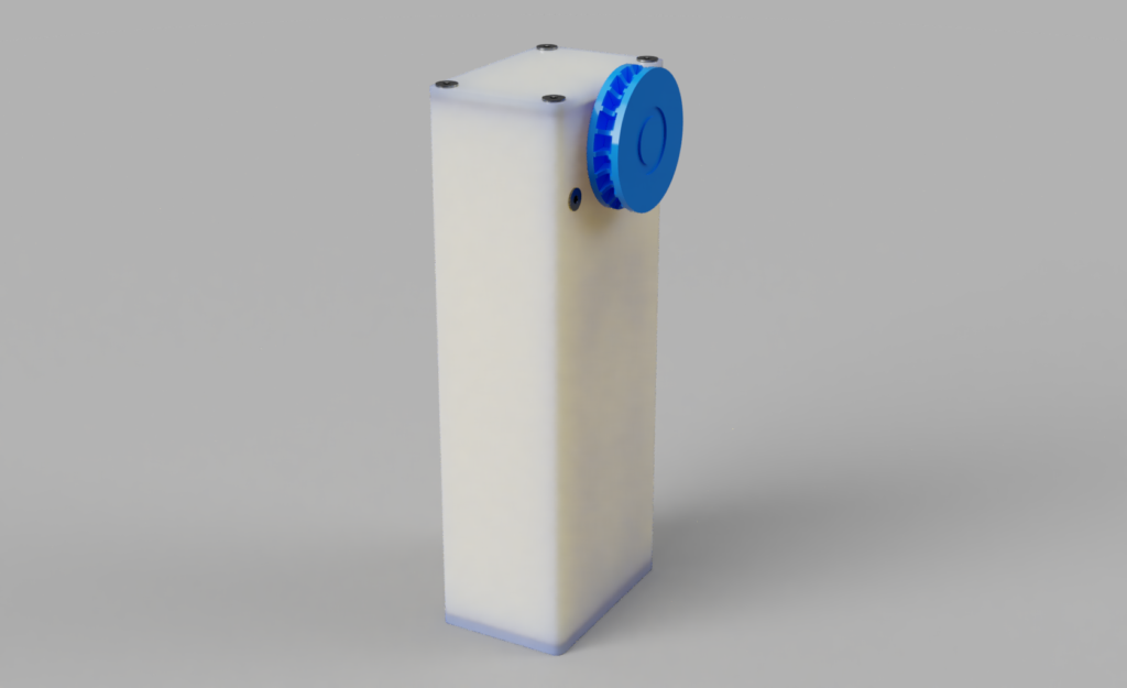
Assembled Body 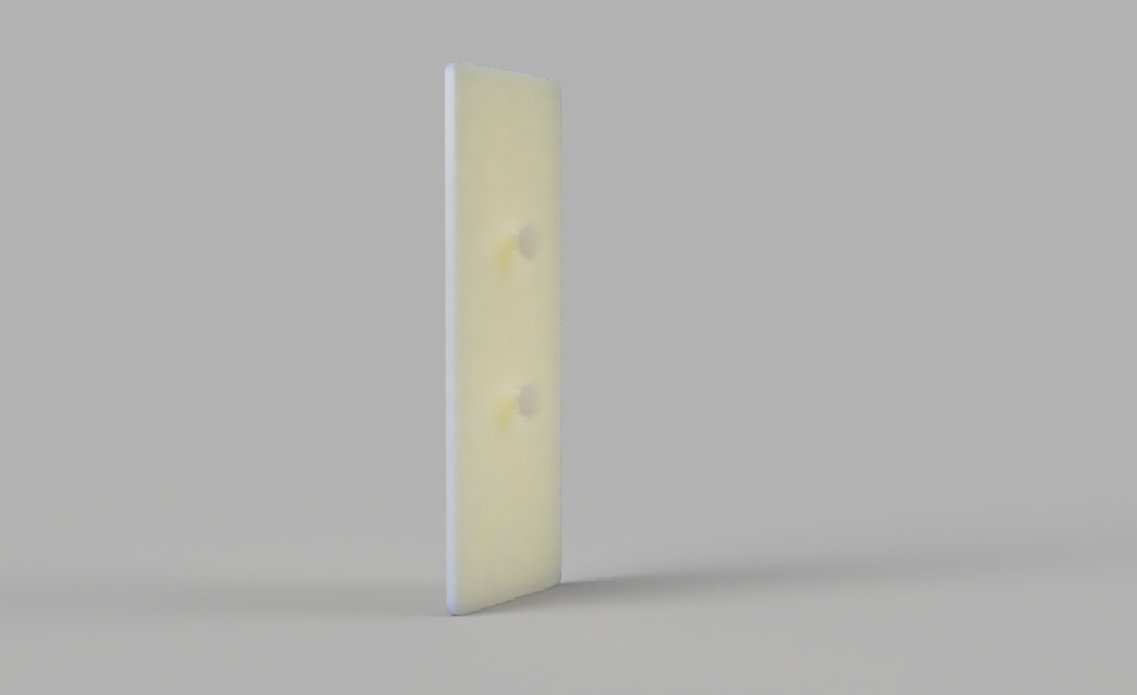
Optional Wall Mount 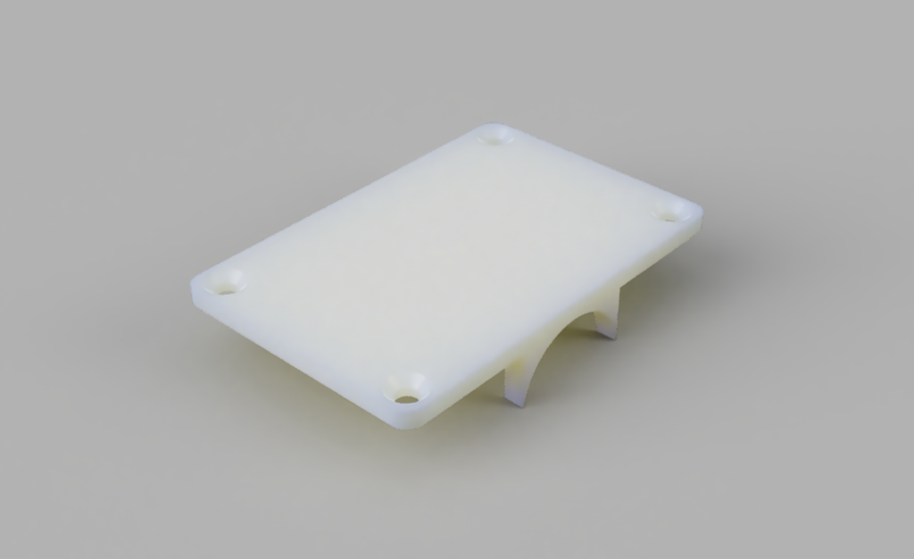
Top Lid 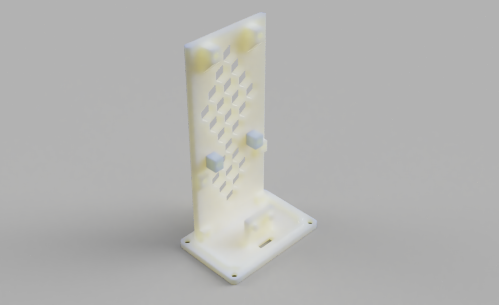
MCU Mount & Bottom Lid 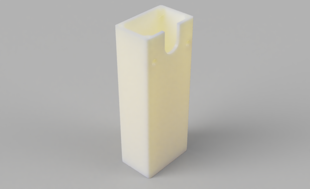
Body
Additional Components
You will require these additional components to complete the assembly. These are all easily obtainable online.
- 1x Node MCU CP2102 ESP8266 (same as DIY SmartBlinds v1)
- 1x Stepper motor 28BYJ-48 5v with ULN2003 driver (same as DIY SmartBlinds v1)
- 8x M2.5 x 6mm self taping screws (MCU and driver board mount)
- 8x M2.5 x 8mm Countersunk screws (top & bottom lid)
- 2x M2.5 x 12mm Countersunk screws + 2x nuts (motor mount)
- 1x M4 Steel Hex Head Cup Point Grub screw (same as DIY SmartBlinds v1)
- 1x Micro USB Breakout Board – Green PCB!
- 1x Micro USB Cord
- 1x 5v USB Power Supply Arduino Sketch for the Node MDU, also attached to this post.
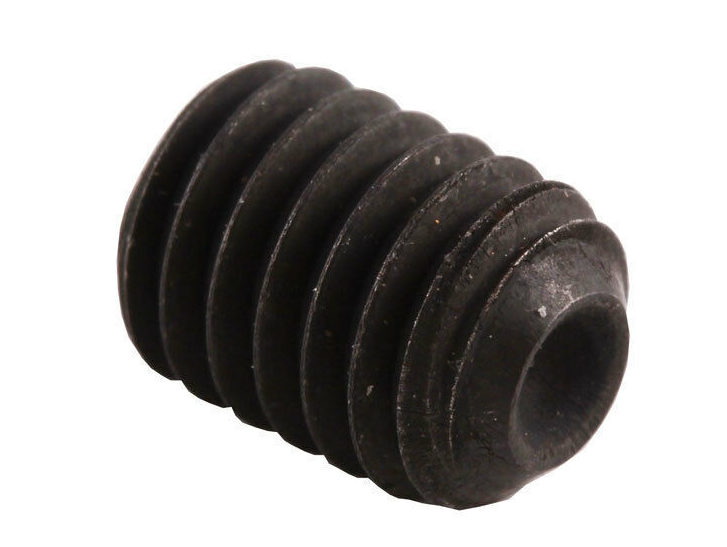
M4x5mm Grub Screw 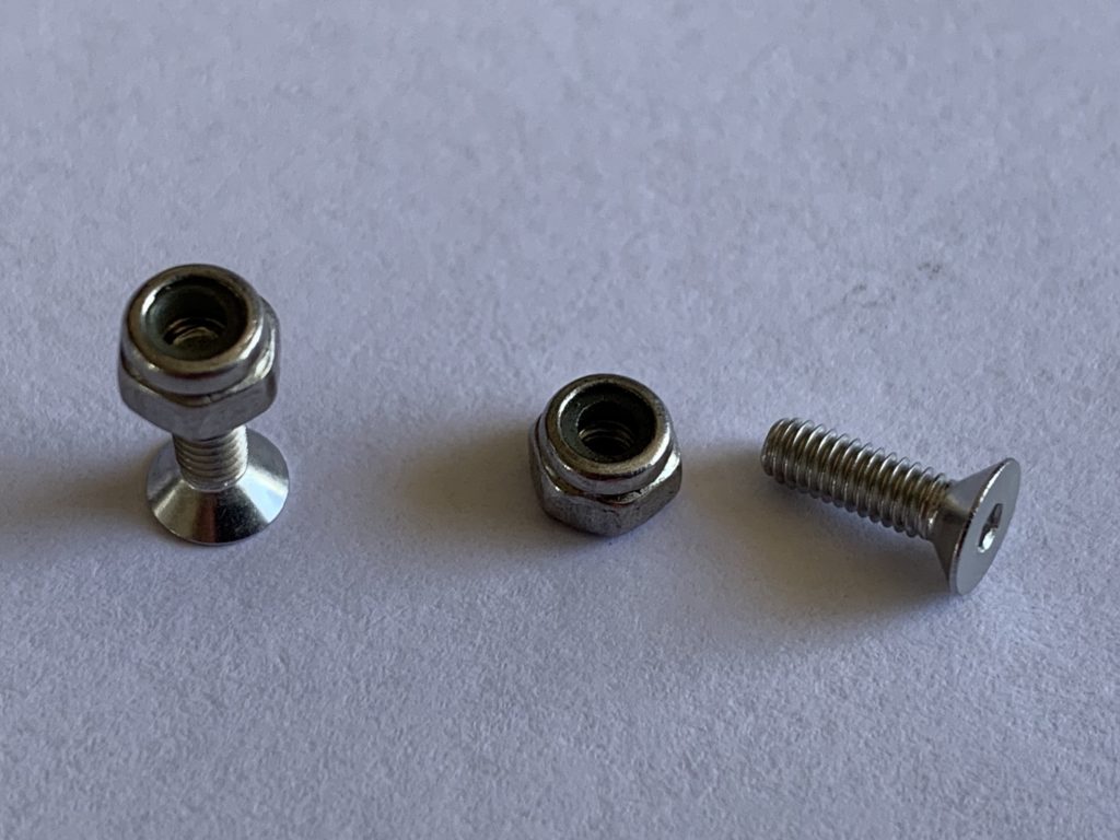
M2.5 x8mm Countersunk screw and nut 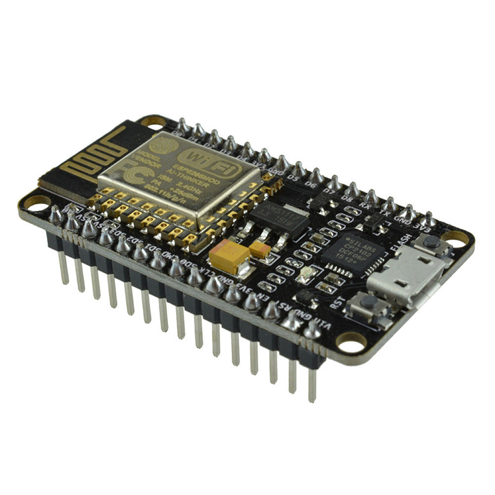
Node MCU CP2102 ESP8266 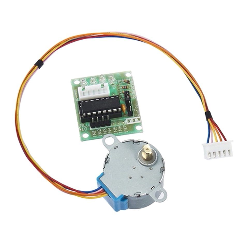
Stepper motor 28BYJ-48 5v with ULN2003 driver 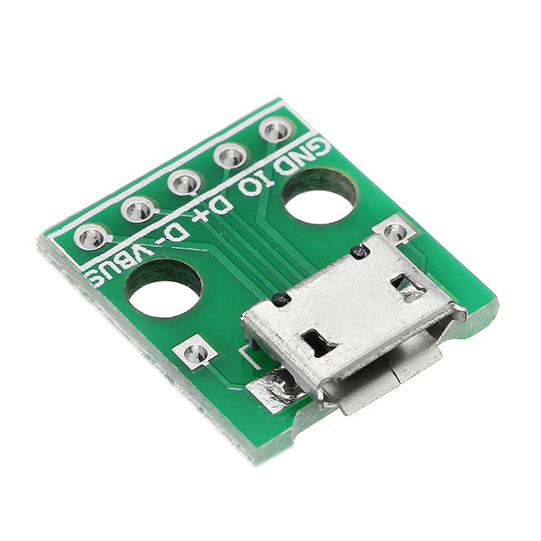
Micro USB Breakout Board – Green PCB
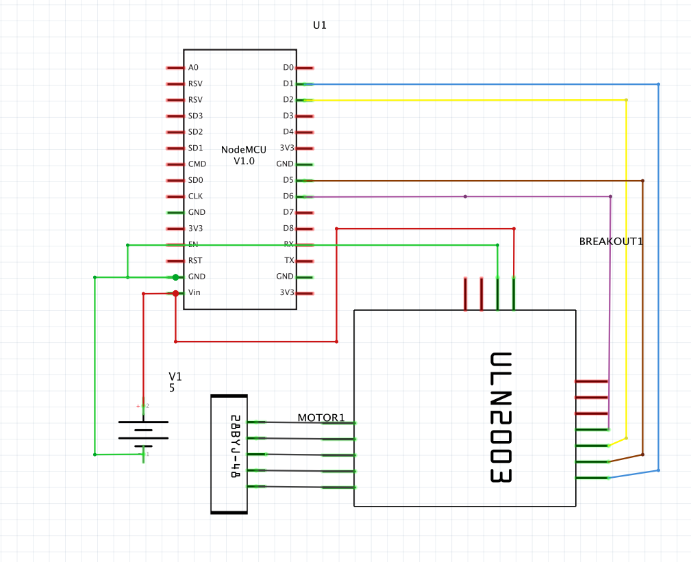
The connection of the electronics components is the same as DIY SmartBlands v1. Here the schematic for completeness. The only difference is that you are wiring up the power to a micro USB micro breakout board, pictured above. Its important you source the breakout board exactly as pictured i.e. the one with the Green PCB, as the mounting points have been designed for this micro USB board. You will also note that this PCB has additional power solder point next to the micro connector. These can be handy to connect power to either the NODE MCU or motor driver. There is another one readily available micro USB breakout board that has a blue PCB. NOTE: This design has not been tested with that PCB design.
Programming
The code for the NODE MCU can be downloaded from GitHub. You can upload the code using the Arduino IDE. There are plenty of tutorials online on the Arduino IDE and how to program the NODE MCU hence I am not repeating them here. I though it would be useful for troubleshooting to post the versions of the libraries that I used for my project. So here they are:
- ArduinoJson 5.13.2
- WiFiManager 0.14.0
- Stepper 1.1.2
- ESP_EEPROM 2.0.0
- WiFi 1.2.7
Home Automation
If you would like to try to integrate the DIY Smart Blinds withe either Apple Homekit (Homebridge required) or Amazon Alexa through the Samsung Smart Things, I am providing my experimental code. Use at your own risk.
| Description | Link |
| Arduino Sketch | GitHub link |
| Homebridge plugin / Homekit | GitHub link |
| Samsung Smart Things – device handler | GitHub link |
What’s next?
I am also testing a simple mod, for this design to make it suitable for Wand type blinds. Wand operated blinds (typically horizontal blinds) have a long wand / stick that when twisted adjust the position of the horizontal blinds.
Let me know in the comments if that type of adapter would interest you or if you have any questions about this new v2 design?
-
 DIY SmartBlinds v2 – STL$3.00