This project aims to upgrade the popular DIY Smart Blinds v1.1 with a Nema stepper motor in order to increase the torque for moving roller blinds. For this project, my biggest concern is the size of the Nema motors. The aim of this version is to keep the form factor of the device as small as possible, give it as much pulling power as possible and allow for a standard 12v power supply. I have estimated that the total cost of this project is between $40 AUD – $60 AUD depending on where you source your components. Below is a short teaser of the project.
The Motor
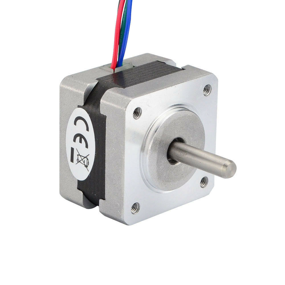
For this project I will use the NEMA 14 and NEMA 17 Stepper motor. The NEMA 14 motor is a smaller alternative to the NEMA 17 measuring at 35mm x 35mm x 26mm. They are both 12v. NEMA 14 has roughly the torque of 14N.cm (20oz.in.) and NEMA 17 44N.cm. compared to the 28BYJ-48 motor used in the previous design which is approx. 2.9N.cm. This should make this devices much stronger (based on estimated values from manufacturers specs, results may vary). The NEMA 17 version may even be able to to pull a small roller-blind. The NEMA motor come in various lengths (depths). For this design I chose to use lengths as follows NEMA 14, 29mm(max) and NEMA 17, 40mm(max).
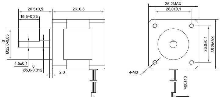
NEAM 14 Dimensions 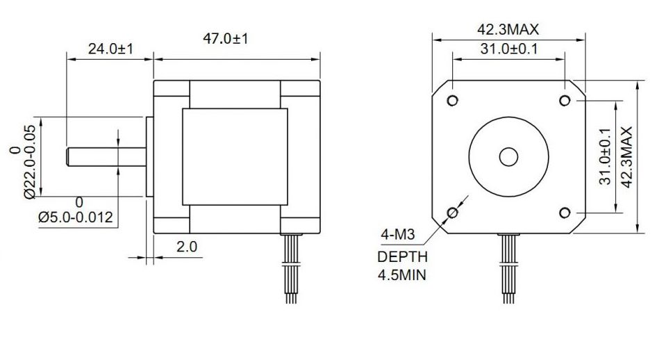
NEMA 17 Dimensions
The Driver
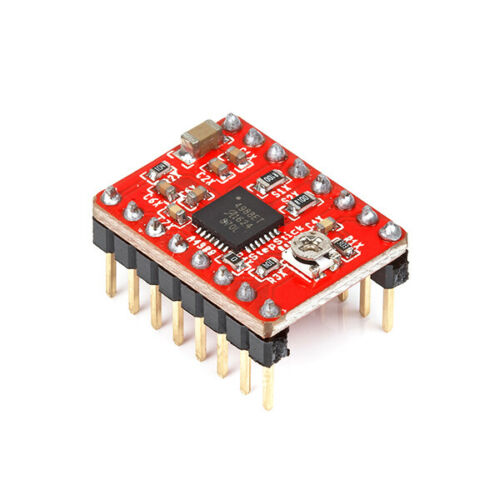
To control the stepper motor, the design should use the A4988 motor driver. It is a noisy driver but it is inexpensive and capable of controlling these motors.
The Processor
I have used the Node MCU ESP8266 processor for many of my projects. It can be easily programmed using the Arduino IDE, its small and it has WiFi built in. Not to mention great community support. Hence for this project I will use it again.
The second option is the NodeMCU ESP8266 WeMos D1. This processor has a smaller form factor and could also be a good choice.
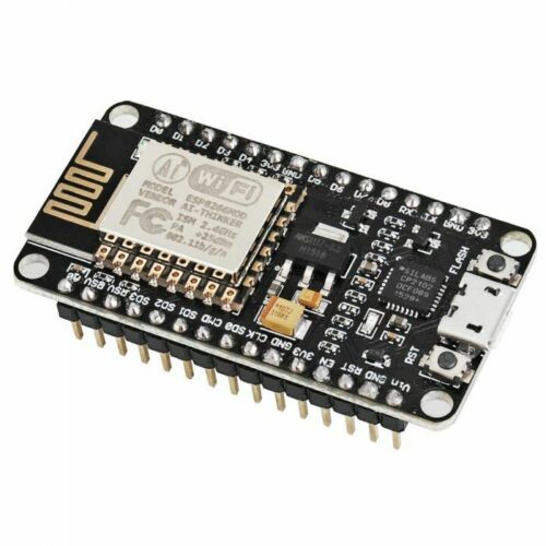
NodeMCU ESP8266 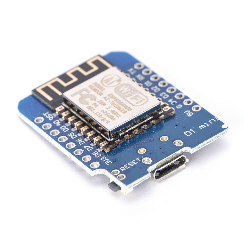
NodeMCU Wemos D1
Considerations
- NEMA 14 or NEMA 17 stepper motors get hot when they run, a 3D printed PLA enclosure may not be able to sustain the heat buildup during operation. Testing shows that typical operation only lasts a 5-10sec then pause. Hopefully this should not raise the temperature too high.
- For this design I have chose the NEMA 14 motor dues to its size but I am also going to make a NEMA 17 variant to get an even more powerful device for those that need it.
- NodeMCU is a better choice because it has VCC in pins. The WeMos D1 needs to be powered through the micro USB port.
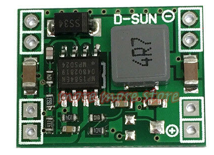
- To power the circuit from one 12v power supply, a 12v to 5v Buck converter will be required. There are various but converters on the market. Make sure you choose one that can handle a current of 1-2A as a stepper motor can be drain quite a bit of current per phase.
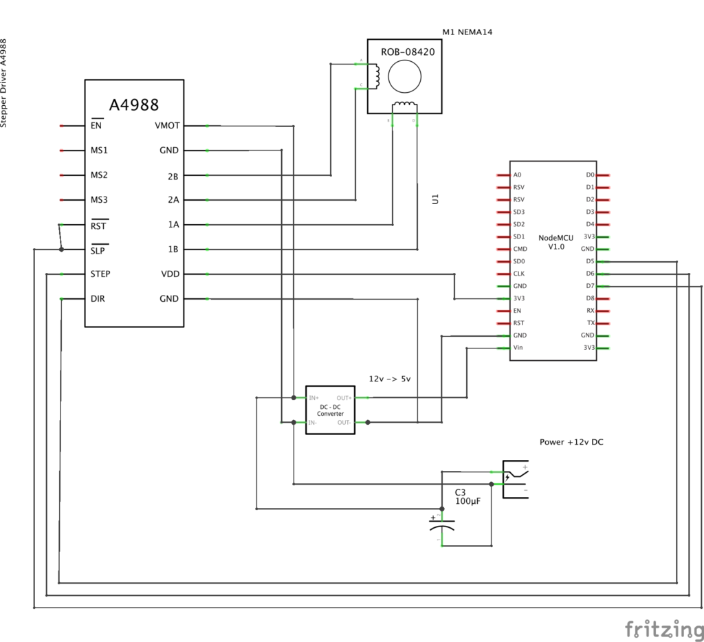
Schematic Diagram
What you will need
- nodeMCU Board
- A4988 Motor Driver
- 12v to 5v Buck Converter
- NEMA14 or NEMA17 Stepper Motor
- 100uF 16v Capacitor on the input voltage
- 5.5mm x 2.5mm DC Power Port
- (8x) 2.5mm x 6mm Button Head Screws (for the lids)
- (2x) 2.5mm x 6mm Self Tapping Screws (for nodeMCU mounting)
- (4x) M3 x 6mm Countersunk Crews (for the motor mount)
- STL Files (link below)
- Software (links below)
Software
| Description | Link |
| Arduino Sketch (this may evolve over time) | GitHub link |
| Homebridge plugin / Homekit | GitHub link |
| Samsung SmartThings – device handler | GitHub link |
The Design Shape
What form factor should the DIY SmartBlinds v3 have?
- Rectangular Shape similar to v2 (54%, 13 Votes)
- L-Shape similar to v1 (46%, 11 Votes)
Total Voters: 24
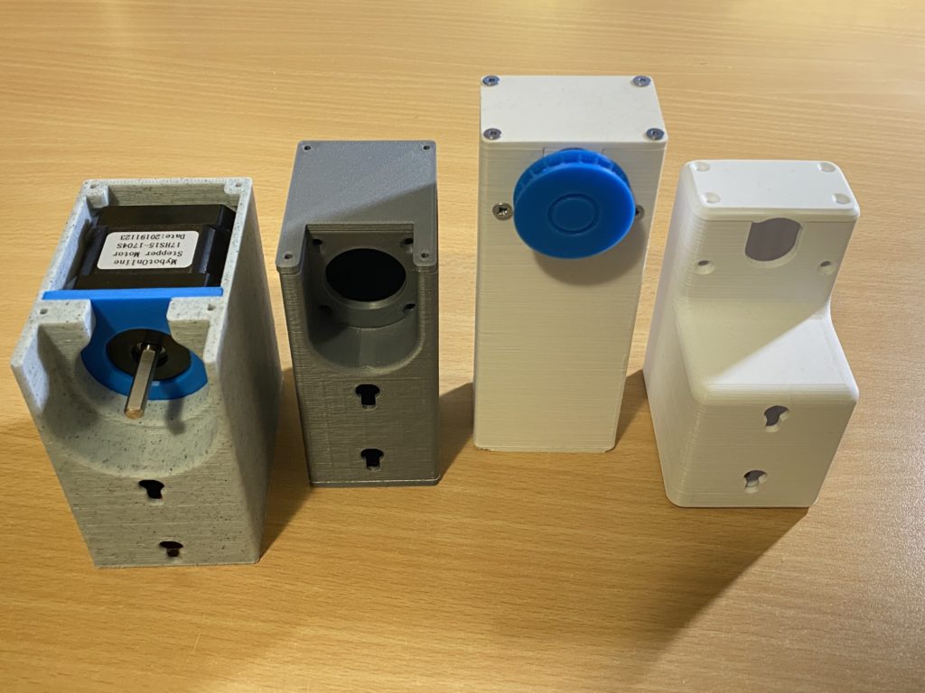
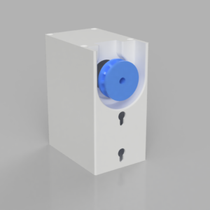
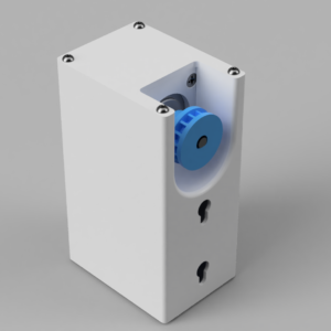
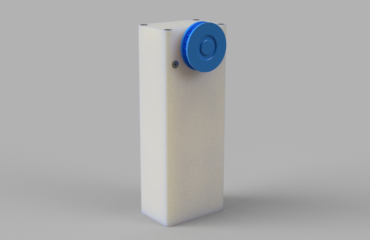
Thank you everyone that participated in the survey. As requested, the design is rectangular. I designed it with a chain guard all inclosed. Checkout the design renders and some first assembly photos below.
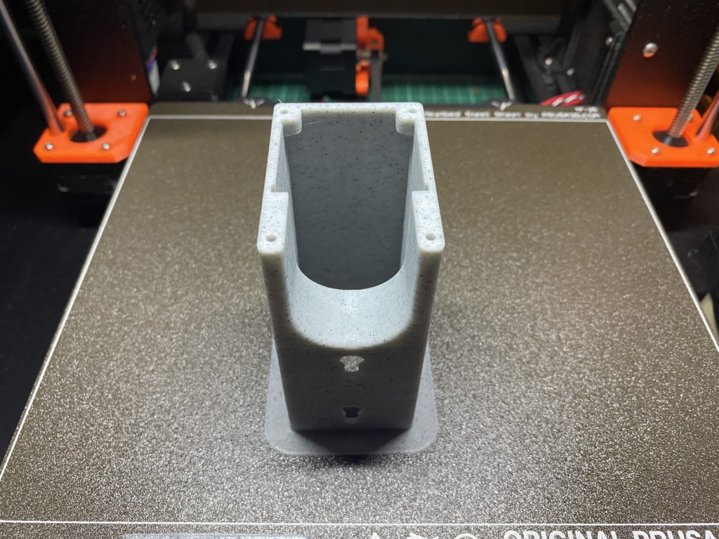
3D Printing
TIP: When printing the main body, print it with a brim. 8mm should be sufficient. Due to the walls on the main body being only 2.5mm thick, I found that when I printed it without the brim the model would get unstuck halfway through and the print was destroyed.


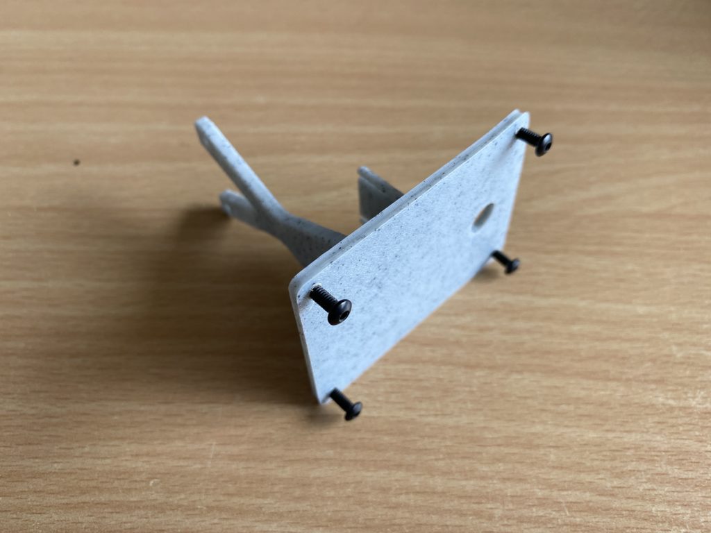
Assembly (NEMA14 & NEMA17)
Always prime all printed holes 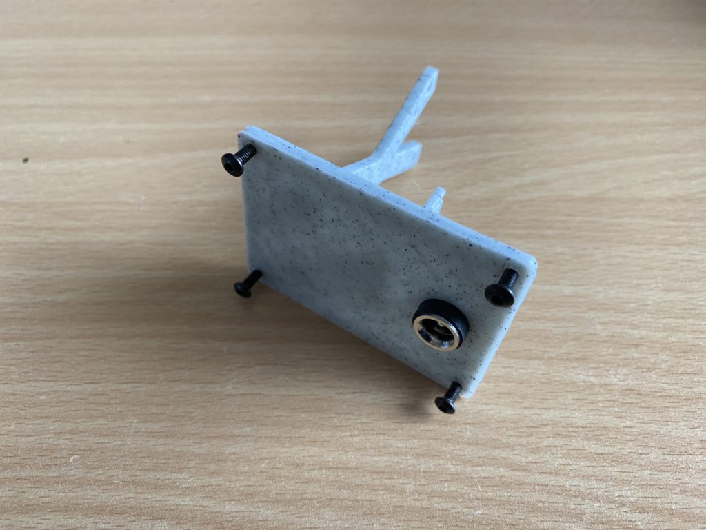
DV plug should just slide in 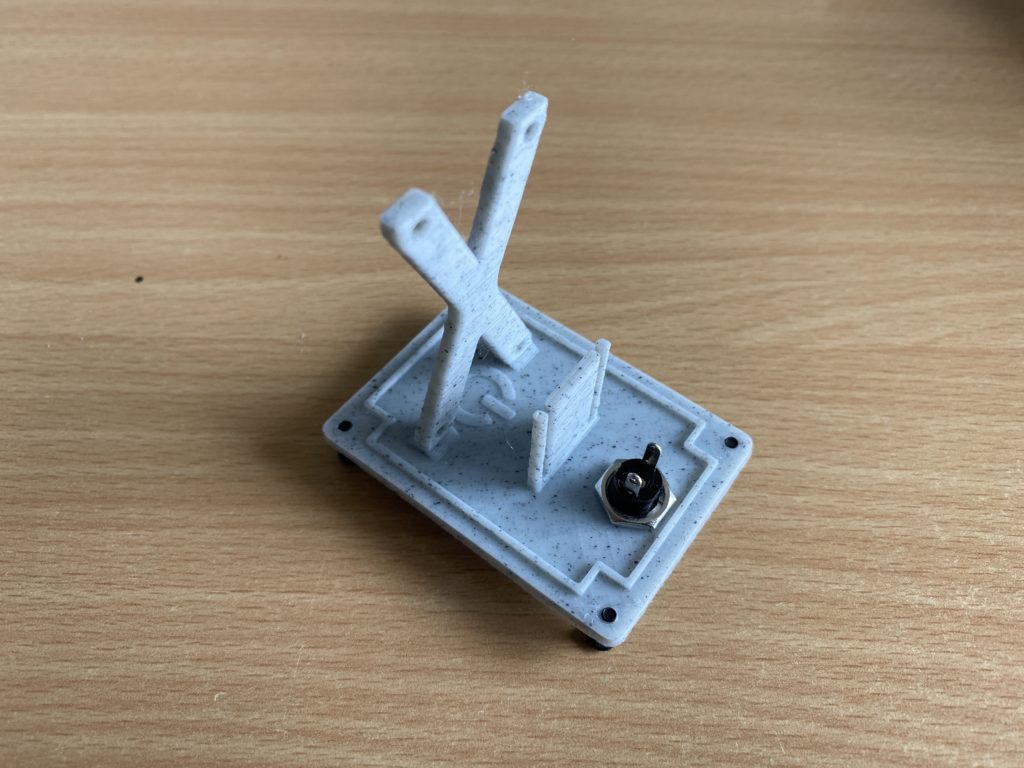
The DC plug screw has a sung fit 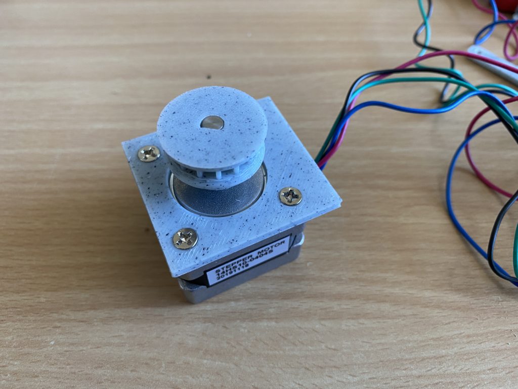
The motor is simple screwed on the motor mounting plate 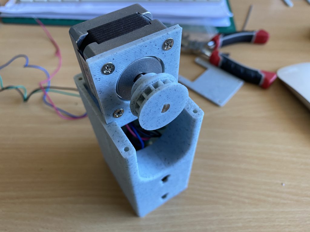
The mounting plate slides into the main body. Its a tight fit, might require some clearing 
The motor as a snug fit 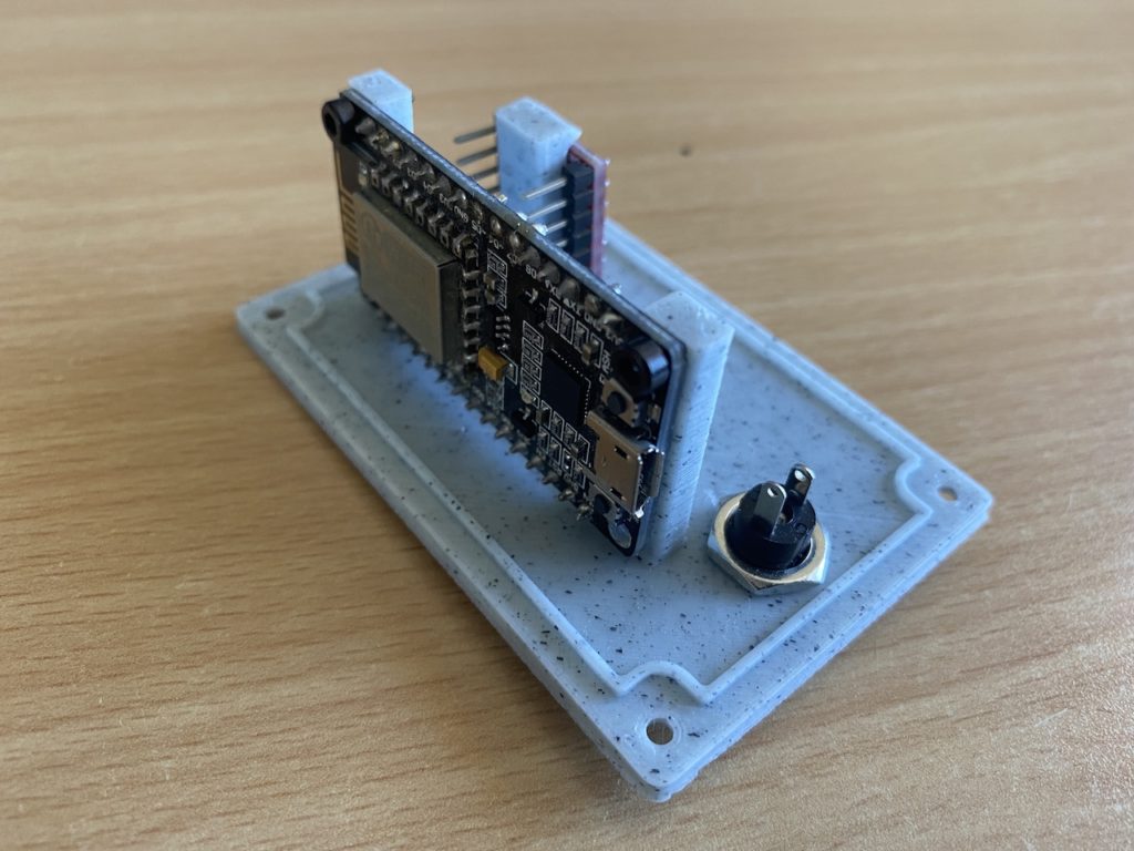
NEMA 17 Suggested NodeMCU mounting position 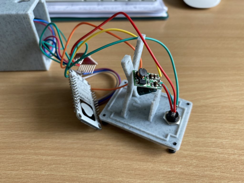
Remove the pins off the nodeMCU for an easier fit 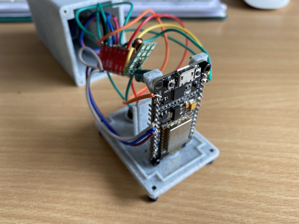
mount the nodeMCU with the USB pointing so that you have easier access when reprogramming 
The driver slides into its printed port. Cable management leaves much to be desired. 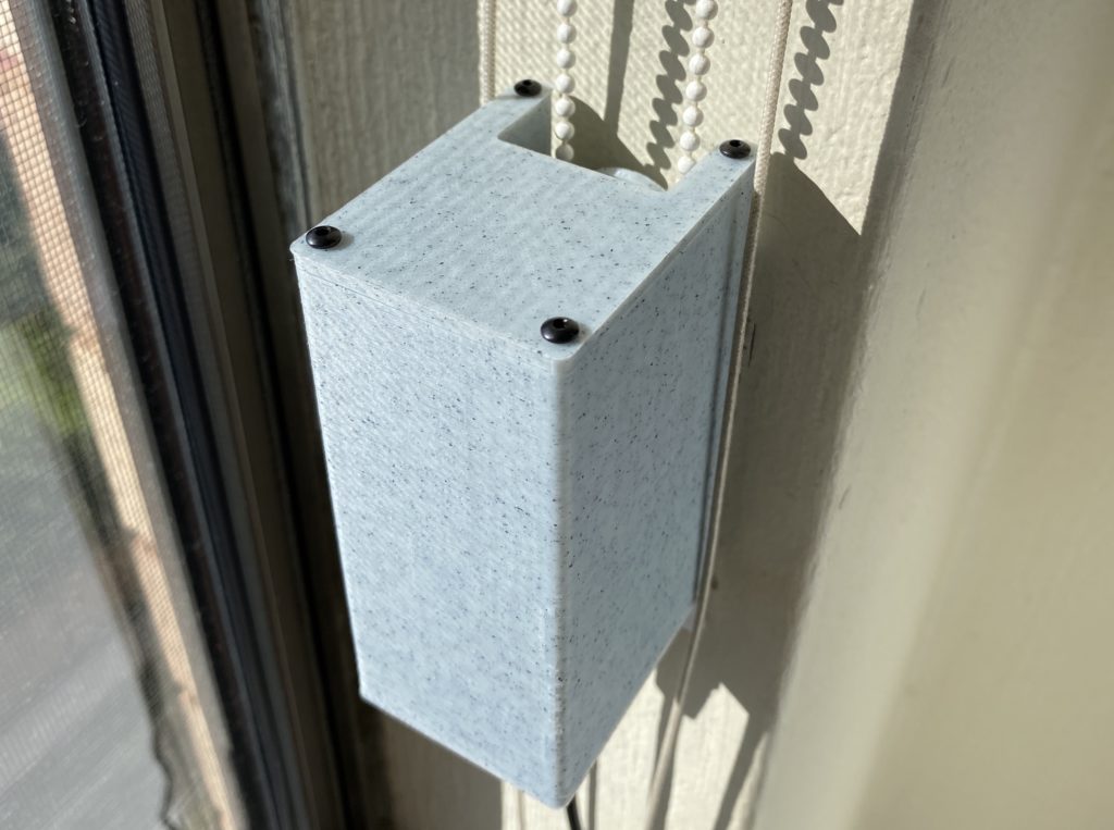
Complete project
I have been messing with your blinds version 1.0 for a bit (in between other projects) and finally got it all working today. However, the torque on the 28BYJ motors is just not enough power to operate my roller blinds. I even tried trimming down the blinds so they were not as tight and rolled as easily as I think possible.
I am very interested in the v3.0 project. I’d like to get started but I am pretty new with Arduino – is there a specific driver board I would use with the Nema 14?
Hi Bert, I think the most cost effective driver will be the A4988 based one. It’s small enough and together with the NODE MCU that should make the setup compact. I don’t like that the Nema 14 has such a long shaft. It will stick out unless the enclosure is a bit thicker. Speaking of enclosures, should the enclosure be similar to the design in V1 or more like V2?
I have just got my drapes sort of working.
Mine are from this instructable……https://www.instructables.com/id/Alexa-Curtain-Control-System-3D-Printable-and-Low-/
Drape size 1600 dropx1500 wide & 1600 drop x 2000wide.
Alexa can operate them 1×1 but not both together in a routine.
my case is 140x80x50 using 47x42x42 stepper motor which i had at the time.
At the moment they are 12v battery operated which is why the case is so big.
Love to see what you get going with the samsung smart things.
Hi Neil, I already have the SmartThings Device Handler built for the DIY SmartBlinds v1 & v2 from my website, You should be able to find the link here: DIY SmartBlinds v1 + SmartThings Device Handler. I am now working on DIY SmartBlinds v3 which will incorporate a Nema14 (35x35x26mm) stepper that is 5x more powerful than the original design. Nema17 would be 10x but its bulky. I want to try and keep this unit as small as possible. Unfortunately I hit set back, I fried 3 of my WiFi NodeMCU and Wemos D1 boards thinking they can handle a 12v input – wrong! I will need to order a few more and use a voltage regulator to drop the 12v to 5v to power the NodeMCU or WemosD1.
Hi peter, been working with the Nema version of the smart blinds, about the hardware, yes a buck converter is needed to step down to 5v, i would go with the buck converter instead of a mosfet or similar, it runs safer and cooler. The issue I had is the software I tried to convert the code to the AccelStepper library with no luck, I believe AccelStepper library is one of the best out there to drive Nema steppers. Let me know if you want me to beta test.
I have a soft tested sketch for the NodeMCU that uses the AccelStepper library. I will post on Github later and a link in the post. you are welcome to test it on your hardware.
Perfect, sure I will test it and get back to you if I find any issue.
I have uploaded the first port of the Arduino sketch if anyone wants to give it a try. Please not the wiring in the schematic diagram. Also if you are not familiar with the A4988 driver, please read up about adjusting it for your specific NEMA motor. You will need to set the current limit on the A4988 to suit your motor for optimal performance.
Hello.
I got this error
[Config] Homebridge Config UI X v4.23.2 is listening on :: port 8581
[7/11/2020, 7:35:37 PM] [Office Blinds] getTargetPosition : 100
[7/11/2020, 7:35:37 PM] [Office Blinds] HTTP bad response (http://192.168.1.100/api/status): connect ECONNREFUSED 192.168.1.100:80
I have no any connection in my “HOME” IOS APP
Please help me to understand what a mistake
This could be related to your device not connecting to your WiFi network correctly. Have you searched for issues relating to WiFiManager? perhaps try a different version of the library? Try reseting your WiFi Settings with WiFiManager and try reconnecting the NodeMCU back to your WiFI network. Hope these help.
Thank you for your answer.
I did many attempts. I think the problem with library, because I even change router, did reset settings and still have nothing.
I have node js version 12.x.x
But required is 7.6
How should I save my wifi settings in wifiManager?
I can’t see any settings in the .ino file
Here are the library versions I used for this project if this helps:
ArduinoJson 5.13.2
WiFiManager 0.15.0
ESP_EEPROM 2.0.0
All libraries are same.
As I see on this page https://github.com/tzapu/WiFiManager/blob/master/README.md
I need to connect (default ip 192.168.4.1) to set up wifi settings
But I can’t open the page 192.168.4.1, 192.168.4.1:8080, http://192.168.4.1:8080
When I connect my NodeMCU devices gin te WiFiManager library, I use an iPhone to connect to the WiFi that the device creates. Then I add my home wifi settings, said and pass and connect. Once it connects, I find it on my home router in the DHCP list. Then I can connect to it directly on port 80. That’s it. I would usually setup a DHCP reservation so that the device does not change its IP when I use it with SmartThings or HomeBridge.
wifi said: DIY-SmartBlinds
but I can’t see it im my wifi list on my iPhone
Perhaps you need to start from scratch. Find the most basic Arduino sketch using the WiFiManager library and see if you can get your NodeMCU to connect.
I flash standart example but I have nothing. May be hardware problem?
Could be. I have a NodeMCU that overheats, yet if I replace the circuit with another it works cold.
Just for last attempt. How can I put ssid and pass on the code directly?
I have never tried that. You may need to refer to forums related to the WiFiManager library on GitHub.
Also please check the dc converter polarity With vmot and gnd lines. Something wrong
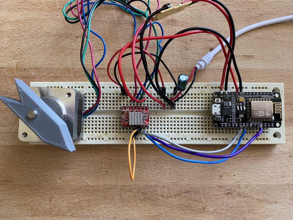
Hi there, I’ve just got this working. Thanks for the great instructions. I’ve made my own case for now but look forward to yours when it’s ready. Everything worked the first time around. Just need to put everything together as it’s on the breadboard at the moment.
Oh yeah, as Mikahil pointed out, the polarity specified for the stepper VMOT and GND in your wiring schematic seems the wrong way around.
Thank you for pointing this out i will update and repost.
Hi, great design!
Two questions:
Can the NodeMCU ESP8266 be powered of usb at 5V?
Does it work with https://www.home-assistant.io/ ?
Best regards
Hi Bo, not unless you can find a motor driver that can power the motor with 5v. I believe such exist but are expensive compared to the A4988. The A4988 requires a minimum of 8v-35v for the motor but the circuit can be powered by 3.3v-5v. Best to check the specs. You will also have to make sure that the stepper motor matches the voltage and power requirements.
Perhaps someone else could comment on this?
As for the home-assistant integration, I am sure you could write a plugin or someone in the community could assist. I have only provided the plugins for SmartThings and Homebridge -> Apple HomeKit.
http://192.168.1.100 what is that IP?
Error processing received information: undefined
what error is that?
Can you please specify which motor model should I buy? I see a few different NEMA 14 constructions. Did you use JK35HY26-0284 ?
I used Nema 14, 14HS10-0404S, 0.4A per phase, Bipolar. I think you can use anyone but you should take care and adjust the voltage limiter on the motor driver.
Thanks for your reply!
Would there be a space for 35x35x28 mm instead of 35x35x26 mm motor? I’m considering buying JK35HY28-0504 over JK35HY26-0284 and then I probably wouldn’t need to adjust the voltage limiter at all.
Additional question:
Can you tell when would your model will be available? 🙂 I’m not in hurry, just asking out of curiosity.
The gap between the back of the motor and the screw mounts is tight. The design has only a 1mm gap behind the motor.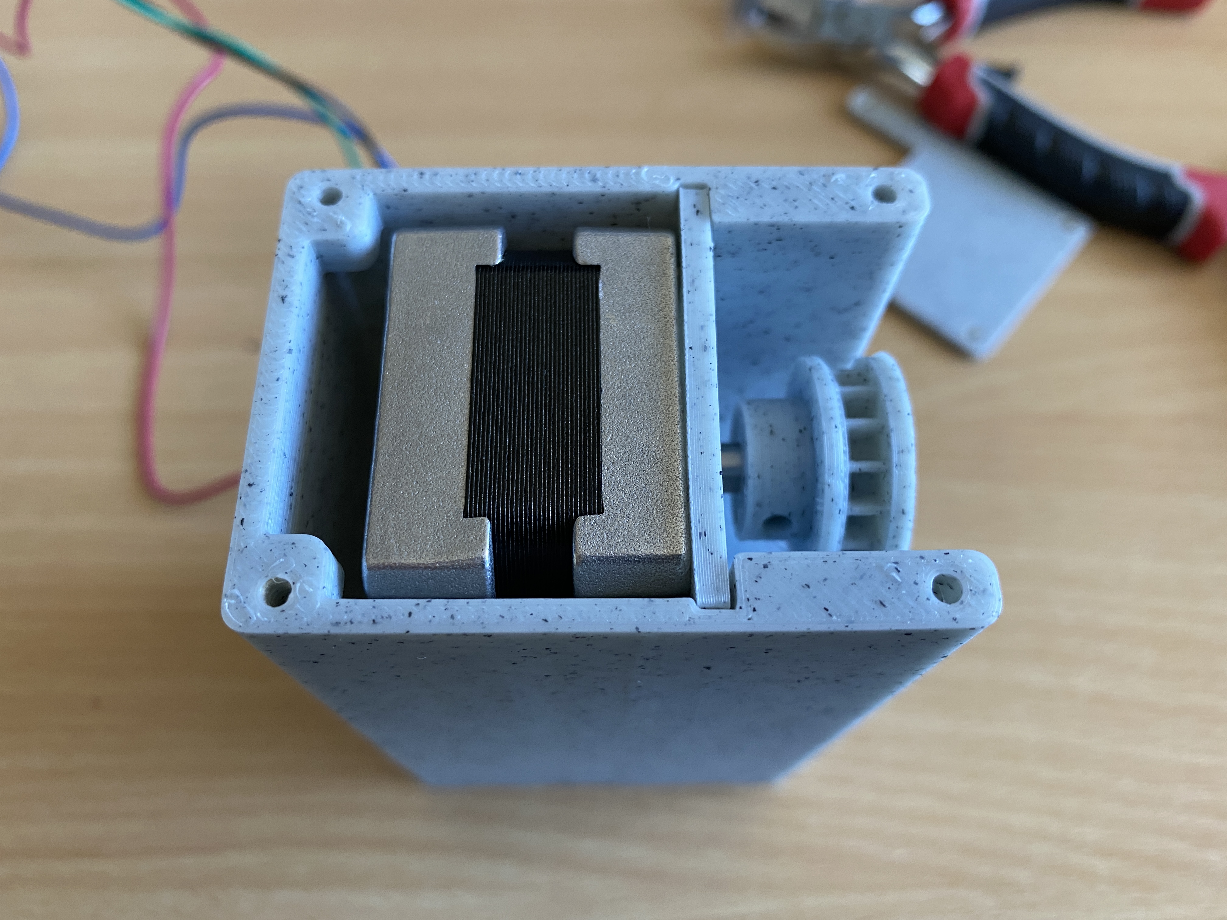
Hi Filip, I just updated the design to accomodate a Nema14 35x35x29mm MAX. You should now be able to first the Nema14’s you wanted to get.
Oh, and I noticed that your model will probably suit only 3 mm string beads. Would it be possible to create something for 5 mm beads in the future?
I have large roman blinds and unfortunately all of them use those thick beads…
Yes I can try to design a bigger cog and add it to the bundle. Can you tell me what the gap between the 5mm beads is?
Thanks, that would be perfect! My beads are actually around 4.60 mm in diameter and the gap is 1.70 mm.
Regarding the gap behind motor – that’s fine. I will just order the smaller one and adjust the voltage then.
I’m also considering “daisy-chaining” multiple units (motors with their controllers, each in separate case) with one ESP module controlling them all. I have wide windows with e.g. 3 separate blinds.
That way I would reduce the cost (less ESPs used), WiFi interference and hopefully some hassle. Do you think that would be a good idea?
That’s an interesting idea. However with one ESP you will need to run at least a 5 core wire between the devices. Maybe you could use a CAT5 cable for this I think they are rated for about 2A.
Hi Filip, I made a cog that may work with your 5mm ball chain. Give this STL a go. DIY SmartBlinds v3 – Cog 5mm
I have some YTDY 5×0.5 mm (0.196 mm2) left so I may try that. For me this cable worked well at a short distance of 5 meters. I’m already powering Sonoff camera (12V, 1A) that way.
For this cable size (0.5 mm diameter) and length of 5 meters – at 2A current flow voltage drop could be around 0.872V. Anyways I will investigate that idea when I have all the components needed 🙂
Hi Peter, I really want to get this working with Alexa but I’m having trouble getting it to work. Can you provide some instructions on how to link it to Alexa please. I tried the SmartThings stuff but I’m stuck. Thank you.
Can you describe what exactly are you having a problem with?
I’ve created a SmartThings account, I’ve added the code for the Device Handler and created a Device. I’m just not sure what I do now. Do I need a SmartThings hub for this to work?
Hi Ali, yes if you want to automate the blinds, I.e. open them or close them at certain times, then you will need a hub. If you are integrating the DIY SmartBlinds with smartthings then you will need the SmartThings Hub. You can also integrate the SmartBlinds with Apple HomeKit but you will require a Homebridge (it’s another kind of hub that works with HomeKit) Once you have the SmartThings hub, you can also connect Alexa to it and operate the blinds vie voice. However, please be aware that as of this writing, Alexa can only respond to “switch the blinds on” or “switch the blinds off” to open or close them. Amazon is working on this and looks like a solution is coming soon.
Personally I don’t bother with voice control of the blinds, mine just open at sunrise and close at sunset.
Thanks for your reply!
Would there be a space for 35x35x28 mm instead of 35x35x26 mm motor? I’m considering buying JK35HY28-0504 over JK35HY26-0284 and then I probably wouldn’t need to adjust the voltage limiter at all.
Additional question:
Can you tell when would your model will be available? 🙂 I’m not in hurry, just asking out of curiosity.
Hi Filip, I am testing the 3D design now. I hope to make the STL files available this weekend for a small gratuity 😉
Thanks Peter, that makes sense. I’ve actually managed to get it working with Alexa by using the home bridge plugin which allows control through Siri on my phone. I then installed the Alexa-Homebridge plugin which made it controllable through my Alexa devices. I can now say “open the blinds” and “close the blonds” through Alexa and it works great. Took a few steps to get there but is perfectly how I wanted it now. Thanks
That’s great. How responsive are the blinds when using Alexa through homebridge?
Hello. If I want to use tmc2208 drivers
What wiring diagram should be?
#define dirPIN D5
#define stepPIN D6
#define sleepPIN D7
#define hotPIN D8
Thank you.
Hi Mikhail, I am not using D8, I will remove it from the code when cleaning up. As for the TMC2208 driver module, please refer to this pinout TMC2208 PINOUT From the diagram STEP -> D6, DIR -> D5, ENABLE -> D7.
Hi Peter, This is a really awesome project and it’s great that it makes use of the NEMA as some of my blinds are quite heavy for the smaller steppers. I had a go at designing this in Fusion 360 while waiting for your design just for fun (not as good as yours, but I got fairly close), and it got me thinking if it would be possible to add up/down/stop buttons and some sort of interrupt to the code to manually open/close the blinds with these? I have 2 Zigbee IKEA blinds connected to my Smartthings hub at the moment and every now and then find I need to manually use the buttons if the WiFi has gone down. I’m worried opening by hand when the device is connected to the chain might cause strain and break it eventually. Thoughts?
Otherwise, any chance you will be making the Fusion360 file available too, as I was thinking of trying to add a hole for the buttons myself, and perhaps a few slits for ventilation. (The nodeMCU I use to control my garage currently gets a tad hot sometimes in its 3D printed box, and the Arduino Uno I had before that kept freezing in summer).
Cheers!
Hi Dale, Thank you for your comments. Unfortunately I will not be releasing the source Fusion files. The STL files should be available this weekend.
I stayed away from manual controls as this project was all about automation. Having said that, the thing about the Nema motors is that if you are not running current through them, they spin fairly easily. So you can safely use the chain to open the blinds.
For roller blinds, I am not sure that the Nema14 will be strong enough. I think you would need the next size up Nema17 at twice the torque.
The blinds are very responsive, if I say “Alexa, close the living room blinds”, they start closing within a second or two. I’m just soldering the components together now so once I’m done I’ll create a video and post the link here so you can see. By the way, do you happen to have an STL file for the bead chain pulley as that’s the only thing I need now. I was going to find one online but if you have one that would be great. Thanks.
Hello. When using TMC2208 should I change something in ino scetch?
Thank you
I don’t have any experience with the TMC2208 driver but from the looks of things there is nothing you need to change. Have you looked up any guides on how to use it with Arduino and a Nema motor?
Hi guys. It is a very interesting project. But A4988 driver is very loud. I trying to update it with TMC2208. It should make blinds noiseless. But Now I can’t understand what is wrong. Can’t start my driver for now.
I connect d5 -> step d6-> dir
d7 -> Enable. Also motor pins were changed. But still nothing.
Does somebody know the reason?
Thanks
Hello. Any one who want to use TMC2208 driver with this excellent project should change
digitalWrite(sleepPIN,HIGH); To LOW.
And
digitalWrite(sleepPIN,LOW); to HIGH
in the sketch. Because tmc2208 use reversing protocol on EN pin.
Thank you for posting. I am keen to try this driver myself due to it being quieter. Have you done any comparisons between the A4988 and TMC2208 in this respect?
Hi Peter.
Please explain me how to add one more more motor and One more device in the ios homekit?
Thank you
If you are using Homebridge and my accessory plugin, then you just replicate your settings changing the IP of the DIY SmartBlinds device in the accessory plugin. You can add as many SmartBlind devices into the Homebridge setup as you want.
Hi Peter, so I finally got around to trying this out on my blinds but unfortunately it doesn’t work. The stepper motor I’m using just clicks and doesn’t appear to have enough torque to actually move my roller blinds. The torque on my stepper motor doesn’t seem to be very powerful, is there anything settings wise that you think may help. The model number of the stepper motor I’m using is SM-17HS4023. Any help would be appreciated. Thank you.
Hi Ali, roller blinds are typically very heavy. Most solutions that I saw were motors built into the roller itself and not chain operated. Having said that, have you tried adjusting the voltage limiter on the driver board? Perhaps it’s not getting enough power?
Sounds like to have a good lab setup for testing, you should also get a Nema17 Motor, these are rated at about double the torque of a Nema14, and see if that will operate the blind. I would be very curious to find out. If Nema17 would do the job, making a 3D printable enclosure would not be a problem, it would just be slightly bigger than this one.
TMC2208 driver make blinds absolutely noiseless. I can hear only ball chain rustling.
[If you are using Homebridge and my accessory plugin, then you just replicate your settings changing the IP of the DIY SmartBlinds device in the accessory plugin. You can add as many SmartBlind devices into the Homebridge setup as you want.]
But I want to use one ESP6288
and 3 motors with one module. So I want to make separate control of each motor.
I see, in that case you would probably need to connect each of the motor drivers separately to you main nodeMCU. Then rewrite to software to allow you to control them individually. You would need to modify the API as well such that you can send independent commands to each of your blinds.
Hi, I am considering making a smart blind controller. But I wondered how much weight the NEMA 14 can handle before I order my parts. Does anyone have experience with this? I have 2 roller blinds of approximately ~ 2.30m and ~ 0.60m.
Hi Peter.
Could you explain how to calculate motor spins with HomeKit target position
I mean Arduino code
hi like the project do you think it would work with GM4632-370 DC 12V 30RPM High torque Turbo Encoder Motor Worm Geared Motor Reducer Motor, just I built 3 blind opening units and its ok but think yours is better and has HomeKit option, if it would work would it be easy to convert the code to use this motor. just a thought could you include button on front to use manual option to open the blind and everyone loves a led option to give status of the device. thanks in advance will start looking at this very soon.
Hi David, I am sure it’s possible to build a device that uses the GM4632-370 DC motor you listed and that has external buttons and LEDs for feedback. It would need to be a completely new project with a redesigned enclosure.
If it’s HomeKit integration you are after, then perhaps you can adopt the code for the API from my project, then you would be able to use the HomeBridge plugin as is?
Thanks Peter will purchase stl files and use yours as a starter and see the options, many thanks for the reply.
what I am to get is the blinds into home assistant as I run around 60 devices in HA.
Unfortunately I don’t have any experience with Home Assistant. Perhaps one of the raiders here could assist?
The best choice for you would be to use ESPHome 🙂
Hi!
Would it be possible for you to create a version of this project with mounting holes on the side of the case? Assuming that the cog side (with the holes) is front (facing me), I would need to have them on the right side of the case.
I’m not familiar with editing STL files (tried that before) so it would be much helpful for me if you could prepare different versions of this project.
Thanks!
Actually I’ve just realized that sometimes I would need them on one side, and in other cases on the other.
That is because my roman blinds are mounted outside of window recess. And beads chain sometimes is on the left and sometimes on the right side of it.
Thanks again!
Other than mounting the device on the other side, you would probably need to modify the code and change the direction of the motor?
You’re right 😉 However, I will probably use ESPHome to control ESP8266 as I’m using Home Assistant solution for my smart home (those two integrate natively). So I will do coding myself in ESPHome.
Anyways, thanks for pointing that out 🙂
Is it possible for you to prepare two additional STL files (design variants) with holes moved to the one and the other side of case? If so, I would like to kindly request that 🙂
I’ve just bought and downloaded your design but there’s still only one variant. It would be much helpful for me. Thanks!
Done, I have emailed you the STL and also updated it in the product downloads.
Hi. Anybody got TMC2208’s to work? What is needed in the sketch? Absolutely great project!
Uh.. addiditonal question. (Pardon me for being so obtrusive.)
Is your motor shaft rounded or kida truncated? I’ve just noticed that 3 motors that I order have totally rounded section shape. I’m wondering if It would be a problem… Probably I would need to glue cog into that or use some screw to fix it in place.
Hi Filip, the motor I bought had a notch in the shaft. I have put a M3 grub screw hole In the side of the cog so you should be able to fasten the cog on a round shaft also.
You’re my hero <3
So I picked up some DOIT ESP32 devkit v1 boards to use with this project – have already bought the STL files, but will need to do some ‘remixing’ to fit the bigger board as it’s a solid 9mm taller. Will require adding more height to the body shell too.
The other thing I’m finding is that the screw holes are too small. In general my printer is dimensionally accurate, but the screw holes aren’t anywhere near approaching 2.5mm. I’ve modified horizontal expansion but that’s something I’m going to need to keep playing with.
Hi Alan, as you know in 3D printing there are many variables that influence the result print. In the design, the top and bottom holes are set to 2.5mm in diameter. Taking into account filament shrinkage, when printed on my Prusa MK3 i3 printer, the result holes are about 2.2mm to 2.3mm. This is perfect because it allows the 2.5mm screws to grip the plastic. I always recommend to clear the holes by hand with a small drill bit to prevent the plastic over stressing and cracking. Hope this helps.
Hi Peter, yes I’ve been playing a little bit more with my wall flow and horizontal expansion to deal with very minor elephants foot – and hopefully I’ve tightened my tolerances enough to get it right!
I’ve also discovered a smaller option for the ESP32 type board which seems dimensionally more akin to the Node MCU, so will give that a try.
Hi Peter, just wondering what the specifications on that capacitor are as it’s not in your BOM? I can see it’s 100uF and electrolytic, is there anything else I need to know? Is it a particular voltage? (sorry, I’m really brand new to electronics!)
Ah yes, thats a 100uF 16v capacitor, it’s meant to protect the circuit and stabilise the input voltage in case there are any fluctuations. I the screws I listed are a suggestion based on the design. You can use different ones if you stay within the width and length dimensions. Otherwise you just need to be patient and take it step by step. Good luck.
Are the wall mounting holes upside down?
No. If you consider that the pull on the device is in the upward direction then the holes start to make sense.
“To power the circuit from one 12v power supply, a 12v to 5v Buck converter will be required. There are various but converters on the market. Make sure you choose one that can handle a current of 1-2A as a stepper motor can be drain quite a bit of current per phase.”
Isn’t the buck converter just powering the MCU? The stepper motor is powered directly at 12v through the driver. In this case why not just get the buck converter directly to 3.3V, so there is no need for the NodeMCU to convert 5V to 3.3V again.
Yes you are quite right. I will update my post.
For anyone using the TMC2209 (probably the whole 22** family, but I can’t confirm as I only have 2209) instead of connecting D7 to sleep (as on the A4988), you connect it to EN, and you need to invert the logic for the pin, so where it’s HIGH it needs to be LOW and vice versa. Mikhail posted this above, but I completely missed it.
Also if anyone is using an ESP32 instead of ESP8266, you’ll need a number of changes to the sketch which is currently available here: https://github.com/crashtestoz/diy_smartblinds_v3/pull/1/files
N.B. that amended sketch doesn’t include the changes above for the TMC2209, you’ll have to do that yourself.
Hi Peter, what’s the best way to increase the RPM? I know there’s a trade-off with setting speed, but would love to tweak it and find the optimum for my setup.
Is it through adjusting the delayMicroseconds argument?
Yes, from memory I believe reducing the delay amount will increase the rotation speed. The only other way would be to introduce a gear system. Are you using the device on a roller blind? Is the motor speed too slow?
Great JOB! I’ve created HomeKit library and used it with your 3d model, check here:
https://github.com/arturkuma/ESP8266-Homekit-Roller-Blinds
Looks great! Whats that sticking out of the side of our device? Are you getting any skipping on rolling up the blinds?
Its for buttons. Didn’t had any in time when I was building it.
There is no skipping at all 🙂
The only problem I had was with my motor – it has rounded shaft, so it’s not that easy to put gear on it. But hot glue helped
Shopping for 12V power supplies. Is 1Amp sufficient? 2amps? 3? Thanks!
2amp will be enough. The max amp of the controller is 2amp and you probably will not run it at full power?
Awesome, thanks!
Hi there,
Great project so far. I´ve got it working with th TMC2208 driver. Noiseless ;).
But everytime I close the blinds via Home-App I get a No Response Error in Home-App. After the Blind is closed / open the error disappeared. No “No Response” in Homebridge.
Already set the DEF_TIMEOUT in “index.js” at 15000 (15sec.?) Is there another option for this “bug”?
Thanks
Hi Timo, I am not aware of a solution for this perhaps someone else here could assist?
Hey All – First off, I love this project.
I got one of these things built using a Nema 17 motor and a 12V 2Amp power supply. And when I run the unit without attaching it to anything it works great.
When I attached it to my shade, though, it didn’t have nearly enough power to move the thing. Meaning, it doesn’t move at all. I watch it try to spin but with no result beyond some loud clicking for 100 steps before it gives up.
I thought it might be the motor so I swapped it out for a different Nema 17 motor that I know works well, but I had the same result.
Then I thought it might just be that I had put it on a large window where the shade was too heavy. Tried it on a small window and still no luck. Tried it at different angles and different levels of tension and nothing.
Since it’s receiving and processing commands I don’t think it’s the processor. Is this something that could happen with a bad A4988? Maybe I need a higher-wattage PSU?
At this point I have no idea how else to troubleshoot. I feel like I’ve already tried replacing the components that are likely to cause this problem. Is the Nema 17 just not powerful enough?
Thanks in advance for any suggestions on what else I might try! I’ve now sunk a lot of time into this project and really want to get it to work!
(Note: I’m using the Wemos D1, but otherwise I’m using the exact same components outlined in these instructions. I found the Wemos a bit more finicky to get up and running than the ESP8266, but eventually it got running and I like having something smaller to work with.)
The only thing that comes to mind is your limiter setting on the controller. Perhaps ist not getting the right amount of current to the motor?
Hi Bob,
my setup is: TMC2208 (Still got it working on a A4988 driver), Wemos D1 mini and a NEMA 17 Motor.
I´ve set the limiter on the driver at like 50%. My blind is 160 cm x 80 cm.
I´m using a 1,5A PSU btw.
My first problem was the gear…it didn´t match my chain. The diameter of one “ball” was 4,5mm and the distance between the balls were like 6mm.
So i was looking for a matching gear on thingiverse and modified it to match the Nema 17 motor.
So does your gear got the “grip” to move the blinds?
Or does is have grip but still no movement to the blinds?
Hope you understand what i mean 😉
Thanks for the ideas! It was gripping the chain perfectly. The issue was that it didn’t seem to have the strength to move the chain. Next I’m going to try a 24volt power supply to see if I can get the Nema17 working. If not, then I’ll only be able to use the Nema17 on my smaller windows.
The other thing I’ve done is redesign everything to work with a Nema23 instead. That seemed to do the trick!
@Peter Chodyra – Let me know if you want the files for the Nema23 version. It was inspired almost entirely by your design with one or two modifications (e.g., can now print without supports), so if you want the design it’s all yours. Just shoot me an email and I’ll respond with the openscad files.
I have posted the wand adapter for SmartBlinds v2 if you are interested. https://www.candco.com.au/product/diy-smartblinds-v2-wand-adapter/
Am I missing some instructions somewhere? I’m kinda new to all of this and have everything downloaded as well as the components… How do I get the library onto the ESP?
Hi Tim, programming the NodeMCU is a whole other subject. I would refer you to this post which should give you a good starting point. https://create.arduino.cc/projecthub/najad/using-arduino-ide-to-program-nodemcu-33e899
If I bought V3.1 do I need to buy it again to get V3.3?
There is minimal difference in the cog only. If you like v3.1 then there is no need for v3.3
Managed to get everything wired up and can connect to the IP address which brings up “DIY SmartBlinds vNema” control panel… However none of the buttons seem to engage my stepper. Can’t quite work out what the cause might be, have double checked my wiring multiple times.
Hello Peter,
Love this project, I plan on making some in the next few months.
Regarding the stepper motors, what sort of weight or more obviously width are they able to handle? I have a 1.8m blind and I’m curious if they would be powerful enough to wind them up/down. Would you recommend the NEMA 14 or 17 for blinds of this width?
Cheers
Jack